
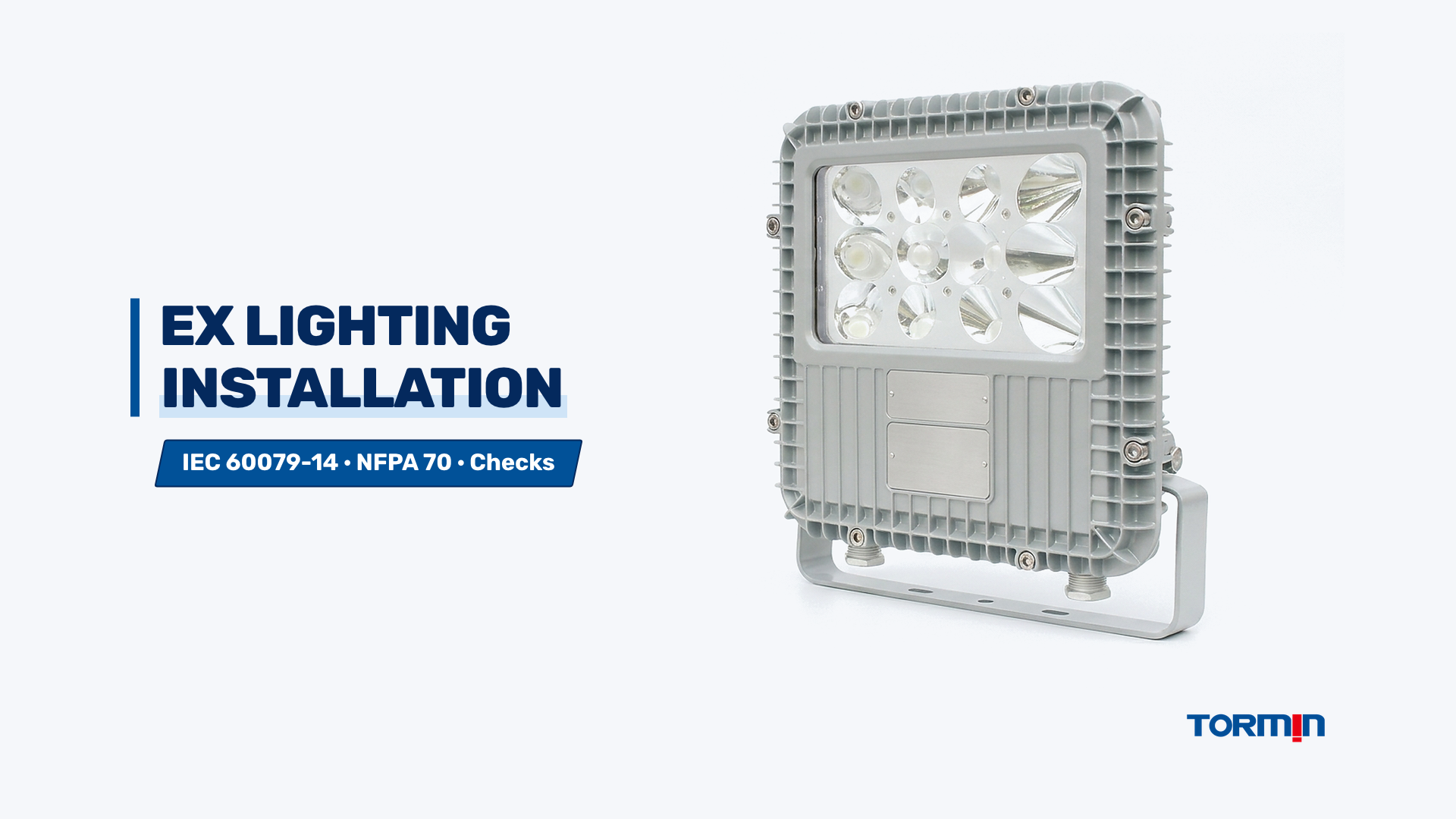
Installing explosion proof lighting requires five bounded engineering stages executed by qualified hazardous-area personnel under IEC 60079-14:2024 or NFPA 70 (National Electrical Code): verifying isolation and exact nameplate-to-classification fit, mounting within permitted thermal orientation, terminating certified cable glands or conduit seals without damaging Ex threads, bonding earth paths and closing enclosures cleanly, and passing initial detailed inspection before energizing.
Mandatory safety prerequisites before touching any luminaire: Confirm that the branch circuit is electrically isolated, locked and tagged out, and tested dead; hold a valid hazardous-area work permit (including gas testing where site rules require it); verify installer Ex competency; and keep the exact manufacturer installation manual and certificate schedule at the workface. Never energize, open, drill, or modify an explosion-proof luminaire outside its documented certification boundaries.
1. Pre-installation verification under IEC 60079-14 and NFPA 70
Pre-installation verification under IEC 60079-14:2024 and OSHA 29 CFR 1910.307 confirms that the physical luminaire delivered to the mounting point matches the controlled area-classification schedule, ambient temperature range, supply voltage, and special conditions of use before any bracket or conduit is erected. Discovering a gas-group, temperature-class, or thread mismatch after mounting forces costly rework and risks energizing non-compliant equipment.
Verify four physical and documentary gates before lifting the fixture:
- Nameplate-to-classification match: Cross-check the physical luminaire nameplate against the project’s controlled hazardous-area drawing (Zone or Class/Division, gas or dust group, EPL/category, temperature class or maximum surface temperature, and ambient Ta range). Area classification itself must already be issued by qualified project engineers; see how a Class, Division or Zone rating is determined and how to read an explosion-proof lighting nameplate and certificate, or decode marking tokens quickly with TORMIN’s Ex marking decoder.
- Special conditions of use (“X” suffix): Review the IECEx Certified Equipment Scheme certificate schedule or North American listing instructions for installation-specific restrictions—such as electrostatic-charge cleaning warnings on polycarbonate lenses, minimum cable-temperature ratings, or prohibited mounting positions.
- Physical receiving condition: Inspect tempered glass lenses, cast housings, machined flameproof joints, elastomer gaskets, and factory entry threads for shipping cracks, gouges, or corrosion. A damaged flamepath or chipped lens is an immediate rejection before erection.
- Accessory and thread match: Confirm that every cable gland, conduit reducer, thread adapter, and stopping plug staged at the workface matches both the luminaire’s certified entry thread form and the terminal compartment’s protection concept.
If the luminaire was selected without a complete pre-installation document record—or if an existing facility is being upgraded—resolve open deviations first via how to select explosion proof lighting for a hazardous area and the explosion-proof LED retrofit site survey checklist.
2. Structural mounting, thermal clearance, and burning orientation for Ex luminaires
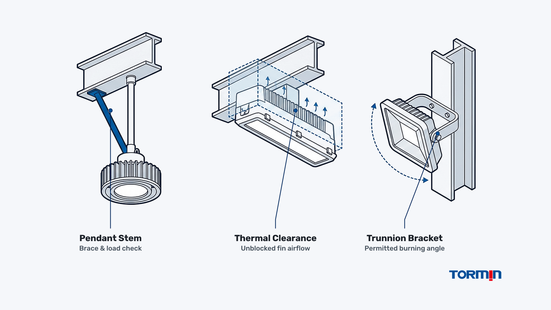
Structural mounting for hazardous-area luminaires must simultaneously support heavy cast-metal loads under plant vibration, maintain unobstructed passive airflow around cooling fins, and respect the exact burning orientation under which the luminaire’s temperature class was certified. Mounting an upright-tested fixture inverted or boxed against hot process piping can push housing temperatures beyond certified limits under IEC 60079-14:2024.
Match the structural mounting method to the luminaire family and site exposure:
- Pendant stem mounting: Typical for explosion-proof LED high bay lights in open process bays. Use rigid metal conduit stems or approved pendant hangers rated for the full fixture weight, and install flexible couplings or diagonal sway bracing where long drop lengths or equipment vibration could fatigue threaded hubs under NFPA 70.
- Ceiling, wall, and surface bracket mounting: Common for explosion-proof LED linear lights along walkways, pipe racks, and pump skids. Secure brackets to structural steel or rated masonry anchors with corrosion-resistant fasteners, leaving clear convection space around cooling fins and unobstructed maintenance access for cover bolts.
- Trunnion U-bracket and stanchion mounting: Standard for directional explosion-proof LED floodlights aimed at tank farms, loading racks, or vertical equipment faces. Lock aiming pivots tightly after alignment and verify that the tilted aiming angle stays inside the manufacturer’s permitted burning-orientation envelope.
- Thermal and environmental clearance: Keep luminaires clear of radiant exhaust ducts, steam headers, and insulated enclosures that trap rising heat. In dusty or oily areas, position housings so fin channels remain accessible for scheduled cleaning, because chronic thermal bottlenecks are a leading cause of early explosion-proof LED light failure.
3. Cable entries, conduit seals, and Ex thread engagement across IEC and NEC systems
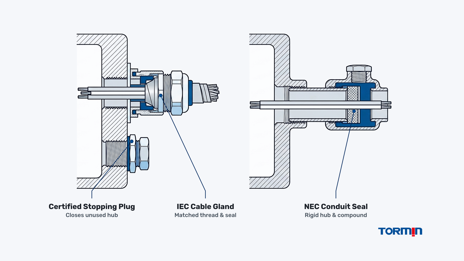
Cable-entry termination is a frequent source of hazardous-area installation non-conformity because IEC 60079-14:2024 Zone cable-gland systems and NFPA 70 North American rigid-conduit systems follow fundamentally different mechanical sealing architectures. Mixing thread forms, omitting certified stopping plugs, or applying unapproved thread sealants compromises both explosion containment and moisture resistance.
| Entry parameter | IEC 60079-14 Zone installation | NFPA 70 Class / Division installation | Hard stop if violated |
|---|---|---|---|
| Primary wiring method | Armored or unarmored Ex-compliant cables terminated via certified cable glands | Rigid metal conduit (RMC/IMC) or approved hazardous-location cable methods | Non-Ex industrial glands or unapproved flexible raceways used inside classified boundary |
| Compartment-to-gland match | Gland protection concept (Ex db, Ex eb, Ex nR) must match the receiving terminal compartment | Conduit fitting and hub must be listed for the required Class, Division, and Group | Ex eb gland installed on an Ex db flameproof enclosure without certified barrier/approval |
| Thread form and engagement | Metric (ISO) or NPT threads matched exactly; parallel threads fitted with specified sealing washer | Tapered NPT threaded hubs engaged wrench-tight to required full threads | Metric gland forced into an NPT hub, or unapproved PTFE tape/RTV smeared across Ex threads |
| Unused luminaire openings | Closed only with certified metallic Ex stopping plugs matching thread and Ex rating | Closed only with listed metallic close-up plugs rated for the Class and Division | Plastic shipping dust caps left installed in energized service |
| Boundary and enclosure sealing | Barrier glands where required by Ex d volume/cable rules; seal integrity critical on Ex nR | Explosionproof conduit seals poured with approved fiber dam and compound at required points | Unsealed conduit acting as a gas passage or moisture pipe into the luminaire hub |
Do not improvise thread matching in the field. If a site conduit thread does not match the luminaire hub, use only a certified Ex thread adapter or reducer approved in the equipment instructions (and never stack multiple unapproved adapters). For detailed entry-accessory selection and unused-hub closure rules, see explosion-proof cable glands versus stopping plugs and TORMIN’s explosion-proof cable glands overview. For when North American Class I Division 1 and Division 2 installations mandate poured conduit seals, see whether explosion-proof light fixtures need conduit seals.
Pay particular attention to Zone 2 restricted-breathing (Ex nR) luminaires governed by IEC 60079-15:2017: their temperature classification depends directly on airtight entry sealing and gasket compression during installation. Review restricted-breathing explosion-proof lighting before installing any Ex nR luminaire.
4. Earthing, terminal wiring, and Ex enclosure closure integrity
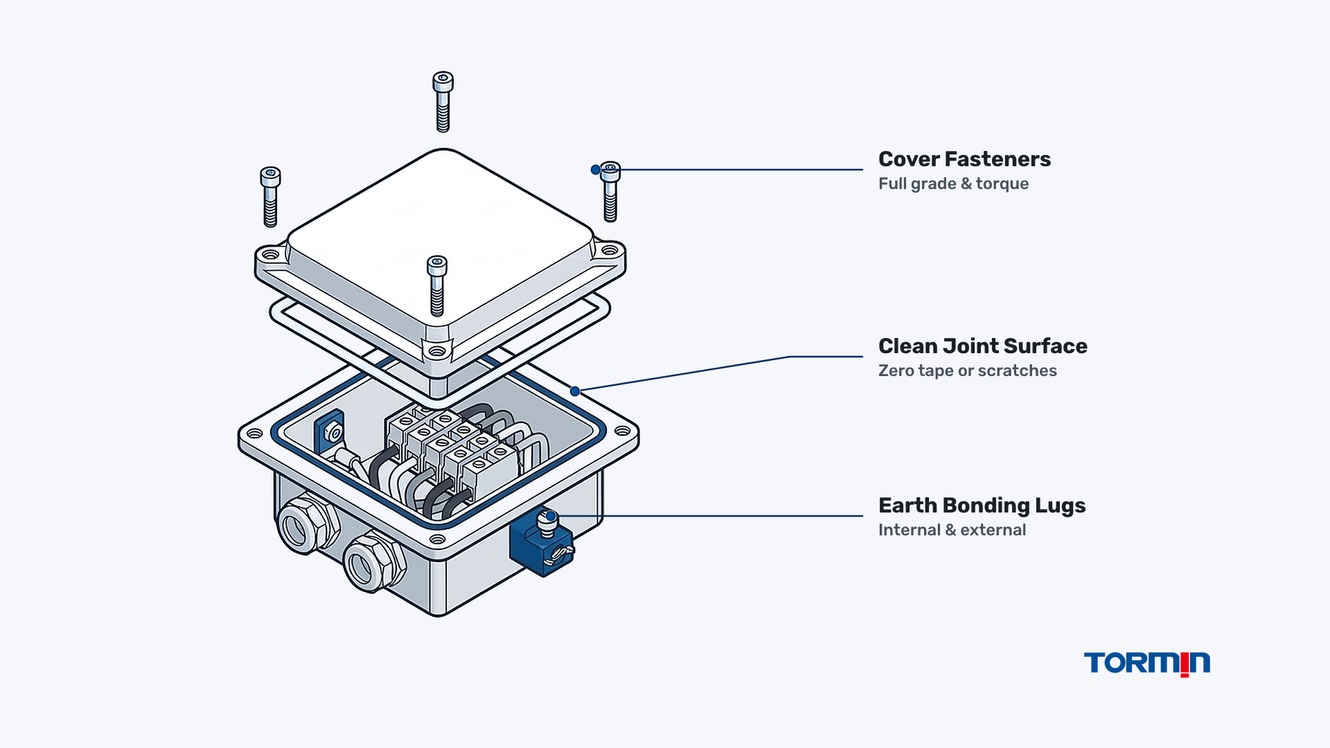
Earthing, internal termination, and final enclosure closure directly govern ignition safety because loose conductors generate resistive hot spots, unbonded metal housings accumulate static or fault potential, and scratched machined joints disable flameproof containment. Under IEC 60079-14:2024, every conductor termination, earth bond, and enclosure fastener must meet the luminaire’s exact assembly instructions before power is restored.
Follow four strict field-execution controls inside and around the terminal compartment:
- Internal and external earthing (equipotential bonding): Connect the circuit protective earth conductor to the internal earth terminal, and bond the luminaire’s external cast earth boss to the facility equipotential bonding grid where project specifications or IEC 60079-14:2024 require supplementary bonding. Verify clean metal-to-metal contact free of paint overspray beneath earth washers.
- Conductor sizing, temperature rating, and torque: Strip insulation cleanly without nicking copper strands, observe manufacturer maximum conductor cross-sections and creepage/clearance rules (critical in Ex e increased-safety terminal chambers), and verify that supply wire insulation temperature ratings satisfy any elevated branch-circuit temperature marking on the luminaire. Where multi-fixture distribution requires external marshaling, route circuits through certified explosion-proof junction and terminal boxes rather than overcrowding luminaire terminals.
- Flamepath and gasket protection: Before closing an Ex d flameproof cover, inspect machined flat or spigot flamepaths for scratches, dents, paint, or grit. Clean only with non-abrasive lint-free cloth and apply solely manufacturer-approved non-hardening anti-corrosion grease if specified—never apply RTV silicone, gaskets not specified by the OEM, or abrasive sandpaper to a flameproof joint. On gasketed Ex e, Ex tb, or Ex nR covers, verify the factory elastomer gasket sits evenly in its groove without pinching or twisting.
- Full-grade cover fasteners: Reinstall every factory cover bolt of the exact material and property class specified by the manufacturer and tighten evenly to the documented torque sequence. Never leave a single bolt missing or substitute lower-grade hardware.
5. Pre-energization initial inspection and hard stop criteria
Pre-energization initial inspection is a mandatory compliance gate under IEC 60079-14:2024 and North American authority-having-jurisdiction (AHJ) acceptance under OSHA 29 CFR 1910.307—never an optional punch-list formality. Under IEC 60079-14:2024, every newly installed luminaire must pass an initial detailed inspection and be logged into the facility’s Ex verification dossier (with equivalent AHJ inspection and compliance documentation under North American codes) before the circuit breaker is closed.
Use this five-stage pass/stop gate table to audit every luminaire before energizing:
| Installation stage | Mandatory physical and document check | Pass criterion | Hard stop / escalate trigger |
|---|---|---|---|
| 1. Pre-installation gate | Nameplate marking, certificate schedule, “X” conditions, and supply voltage vs area drawing | Exact ordering code matches zone/division, group, T-class, and Ta limits | Missing area-classification schedule, unverified scheme acceptance, or shipping damage |
| 2. Structural mounting | Support load rating, vibration bracing, fin thermal clearance, and burning orientation | Rigidly mounted within permitted angle with unobstructed airflow around cooling fins | Fixture tilted outside rated orientation, blocked by hot pipework, or unbraced on vibrating stem |
| 3. Entries and sealing | Gland/conduit thread match, sealing washers, certified stopping plugs, and poured conduit seals | Wrench-tight certified entries on every used hub; certified metallic plugs on all spare hubs | Metric/NPT mismatch, plastic shipping cap left in hub, missing conduit seal, or unapproved PTFE/RTV |
| 4. Earthing and closure | Earth continuity, terminal torque, clean flamepath/gasket seating, and full cover bolts | Verified earth path, undamaged clean joint surface, and 100% factory-grade bolts torqued | Scratched Ex d flamepath, pinched gasket, paint on joint, or missing/substituted cover bolt |
| 5. Pre-energization test | Insulation resistance (de-energized), circuit protection rating, and initial inspection dossier | Electrical test values within code limits; signed initial inspection record archived | Insulation fault, unresolved technical deviation, or unsigned hazardous-area handover record |
Closing the circuit completes initial commissioning; ongoing periodic visual, close, and detailed checks over service life then transition to IEC 60079-17:2023—covered in our guide to explosion-proof lighting inspection grades.
When preparing an installation submittal or confirming mounting brackets, entry thread forms, and exact-configuration manuals for a hazardous-area project, send your area classification schedule, mounting method, and cable or conduit entry specifications through the TORMIN contact page so engineering can supply exact installation instructions and matched accessories before work begins on site.
Sources
- IEC — IEC 60079-14:2024, Explosive atmospheres — Part 14: Electrical installation design, selection and erection — Governing international standard for Ex equipment verification, installer competency, cable glands and stopping plugs, earthing, flamepath/enclosure closure, and mandatory pre-energization initial detailed inspection.
- NFPA — NFPA 70, National Electrical Code (NEC) — Governing U.S. electrical installation code for Class/Division and Class/Zone hazardous-location wiring methods, pendant support, rigid metal conduit, and conduit sealing.
- OSHA — 29 CFR 1910.307, Hazardous (classified) locations — U.S. workplace regulatory requirement for area-by-area classification documentation, approved equipment matching class/group/temperature, and compliant installation acceptance.
- IECEx — Certified Equipment Scheme Overview — Online verification of current Ex Certificates of Conformity, exact covered configurations, and special conditions of use (“X” conditions).
- IEC — IEC 60079-15:2017, Explosive atmospheres — Part 15: Equipment protection by type of protection “n” — Scope and seal-integrity installation requirements for Zone 2 / EPL Gc restricted-breathing (Ex nR) luminaires.
- IEC — IEC 60079-17:2023, Explosive atmospheres — Part 17: Electrical installations inspection and maintenance — Post-commissioning periodic visual, close, and detailed inspection requirements for hazardous-area electrical installations.