
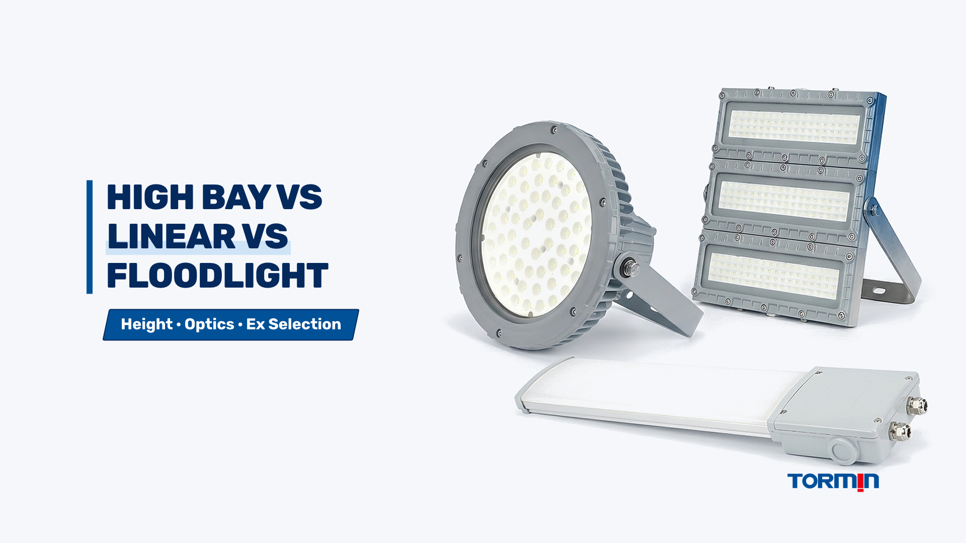
Selecting between an explosion-proof high bay, linear luminaire, and floodlight is an optical geometry, obstruction, and thermal-orientation decision rather than a wattage comparison. Match explosion-proof linear luminaires to 2.5 to 6 m ceilings and pipe-obstructed walkways where wide diffuse overlap prevents hard shadows, explosion-proof high bays to 6 to 15 m open process halls requiring concentrated downward flux, and explosion-proof floodlights to perimeter poles, masts, or structural trusses where light must be aimed obliquely across open yards, tank farms, or loading racks.
Choosing the wrong luminaire form factor is one of the most expensive layout mistakes in hazardous-area projects. A luminaire that carries the correct gas group and temperature class can still fail site acceptance if it casts deep shadows behind valve manifolds, blinds forklift operators at low ceiling height, or overheats because its cooling fins were tilted outside the certified mounting orientation. Before requesting IES or LDT photometric files, engineers should lock the physical form factor using the engineering boundaries below.
Engineering Comparison Matrix for Explosion-Proof High Bay, Linear, and Floodlight Luminaires
Explosion-proof high bay, linear, and floodlight luminaires occupy distinct mechanical and optical envelopes across mounting height, beam distribution, glare control, and wiring topology. Specifying a fixture outside its intended height and aiming window forces either excessive fixture counts or unacceptable uniformity drops under workplace lighting standards such as EN 12464-1 and EN 12464-2.
| Selection Parameter | Explosion-Proof Linear Luminaire | Explosion-Proof High Bay Luminaire | Explosion-Proof Floodlight |
|---|---|---|---|
| Typical Mounting Height (m) | 2.5 to 6.0 m | 6.0 to 15.0 m | 8.0 to 25.0 m (pole, mast, or structure) |
| Primary Optical Distribution (deg) | Wide diffuse or oval (110 to 140 deg) | Symmetric downward narrow to wide (60 to 120 deg) | Directional symmetric or asymmetric (30 to 120 deg) |
| Primary Mounting Orientation | Horizontal ceiling, pendant, wall, or stanchion | Vertical downward pendant, ceiling, or loop-hook | Adjustable U-bracket or trunnion with locked tilt angle |
| Obstruction & Pipe-Rack Behavior | High shadow wrap-around due to elongated aperture | Moderate to heavy hard shadows beneath dense piping | Severe hard shadows if aimed across dense equipment |
| Glare Sensitivity at Low Height | Low (large diffused emitting surface) | High below 5 m (concentrated high-intensity aperture) | Very high if aimed above 45 deg from vertical nadir |
| Typical Power Band (W) | 20 to 80 W | 80 to 200 W | 60 to 300 W (often modular multi-bank) |
| Parallel Loop-In Wiring Fit | High (dual-entry separate wiring chamber common) | Moderate (often requires overhead Ex junction box) | Low to moderate (typically single feed per mast/group) |
| Example TORMIN Reference Family | BC5402A (30 to 80 W, 3,300 to 8,400 lm, IP66) | BC9304P (80 to 150 W, 8,873 to 18,675 lm, IP66) | BC9102S (60 to 300 W modular, 120 to 240 VAC, IP66) |
Use this matrix to assign each facility zone to a single form factor before evaluating lumen packages; if a single building contains both a 12 m reactor hall and a 3.5 m mezzanine pipe gallery, split the bill of materials into high bays overhead and linear fixtures beneath the mezzanine rather than forcing one fixture family across both elevations. Always confirm the exact Ex marking, gas or dust group, T-class, and ambient temperature range for each model reference in its current certificate schedule on the TORMIN Standards and Certifications archive.
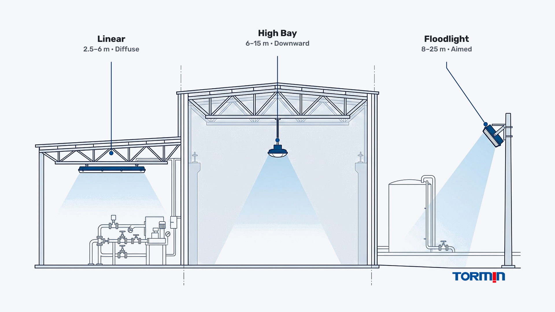
Mounting-Height and Beam-Footprint Geometry Across Hazardous-Area Task Planes
Mounting height and beam angle govern how luminous flux spreads across the horizontal working plane (typically 0.8 m above floor level indoors or ground level outdoors). Because illuminated area expands with the square of mounting height while peak nadir illuminance drops by the inverse-square law, matching beam spread to elevation prevents both wasted wall spill and dark gaps between fixtures.
For a simplified downward symmetric cone, the theoretical floor footprint diameter equals twice the mounting height multiplied by the tangent of half the beam angle. The table below illustrates how identical nominal beam angles behave across three realistic hazardous-area mounting heights (hypothetical geometric footprint before reflectance, obstruction, or maintenance-factor losses).
| Mounting Height H (m) | 60 deg Narrow Beam Diameter (m) | 90 deg Medium Beam Diameter (m) | 120 deg Wide Beam Diameter (m) | Engineering Form-Factor Implication |
|---|---|---|---|---|
| 3.5 m (Walkway / Mezzanine) | 4.0 m | 7.0 m | 12.1 m | 60 deg creates hot spots and dark gaps; 120 deg linear gives smooth overlap |
| 8.0 m (Process Hall) | 9.2 m | 16.0 m | 27.7 m | 90 to 120 deg high bay balances spacing and vertical illuminance |
| 12.0 m (High-Bay / Crane Hall) | 13.9 m | 24.0 m | 41.6 m | 60 to 90 deg high bay keeps flux on the floor instead of upper walls |
| 18.0 m (Outdoor Mast / Yard) | 20.8 m | 36.0 m | 62.4 m | Directional floodlight optics required to control throw and spill |
Do not convert fixture wattage or nominal beam angle directly into guaranteed lux or spacing-to-mounting-height ratios. Actual illuminance and uniformity depend on the luminaire’s candela distribution curve, surface reflectances, dirt depreciation, and maintenance factor, which must be simulated in DIALux or AGI32 using verified IES or LDT files as detailed in our guide on how to read an IES photometric file. For preliminary footprint checks before running full simulations, engineers can test elevation and beam assumptions with the TORMIN Beam Coverage Calculator and Luminaire Quantity Calculator.
When Explosion-Proof High Bays Fail at Low Ceilings (Below 5 m)
Installing a high-lumen round explosion-proof high bay below 5 m concentrates intense luminous flux into a compact optical aperture directly inside the operator’s normal line of sight. Even when average horizontal lux meets the project specification, the high luminance contrast produces discomfort and disability glare during gauge reading and valve operation.
At 3 to 4.5 m mounting heights, a narrow 60 to 90 deg high bay also forces tighter fixture spacing than the lumen package justifies, driving up capital cost and power density. Switching to a diffused explosion-proof LED linear light lowers aperture brightness, improves uniformity between structural columns, and keeps headroom clear above walkways and stair landings.
When Explosion-Proof Linear Luminaires Lose Efficiency Above 8 m
Mounting a wide-beam diffused linear luminaire at 10 to 14 m spreads a large share of output onto upper walls and structural bracing rather than the floor task plane. Reaching 200 to 300 lx on an open floor with 40 to 60 W linear fixtures often doubles or triples mounting points and cable glands.
Above 6 to 8 m in unobstructed bays, consolidating fixture points with an explosion-proof LED high bay light—such as the TORMIN BC9304P family (80 to 150 W, 8,873 to 18,675 lm by configuration)—reduces installation labor, hazardous-area cable entry count, and ongoing IEC 60079-17 inspection points.
Pipe-Rack Obstruction Shadowing and Parallel Wiring Topology
Dense process environments—such as refinery pipe racks, compressor skids, pump-valve shelters, and offshore deck modules—rarely behave like empty warehouses. In these obstructed zones, the physical length of the luminous aperture and the fixture’s internal wiring architecture matter as much as raw lumen output.
A high-output point source (high bay or floodlight) mounted above a 200 to 400 mm process pipe or cable tray casts a sharp, high-contrast shadow cone directly across pressure gauges, sample points, and walkway treads below. By contrast, an elongated linear luminaire (typically 600 to 1,200 mm long) emits light from a continuous diffused surface, allowing rays from either end of the fixture to wrap around pipes and soften shadow edges.
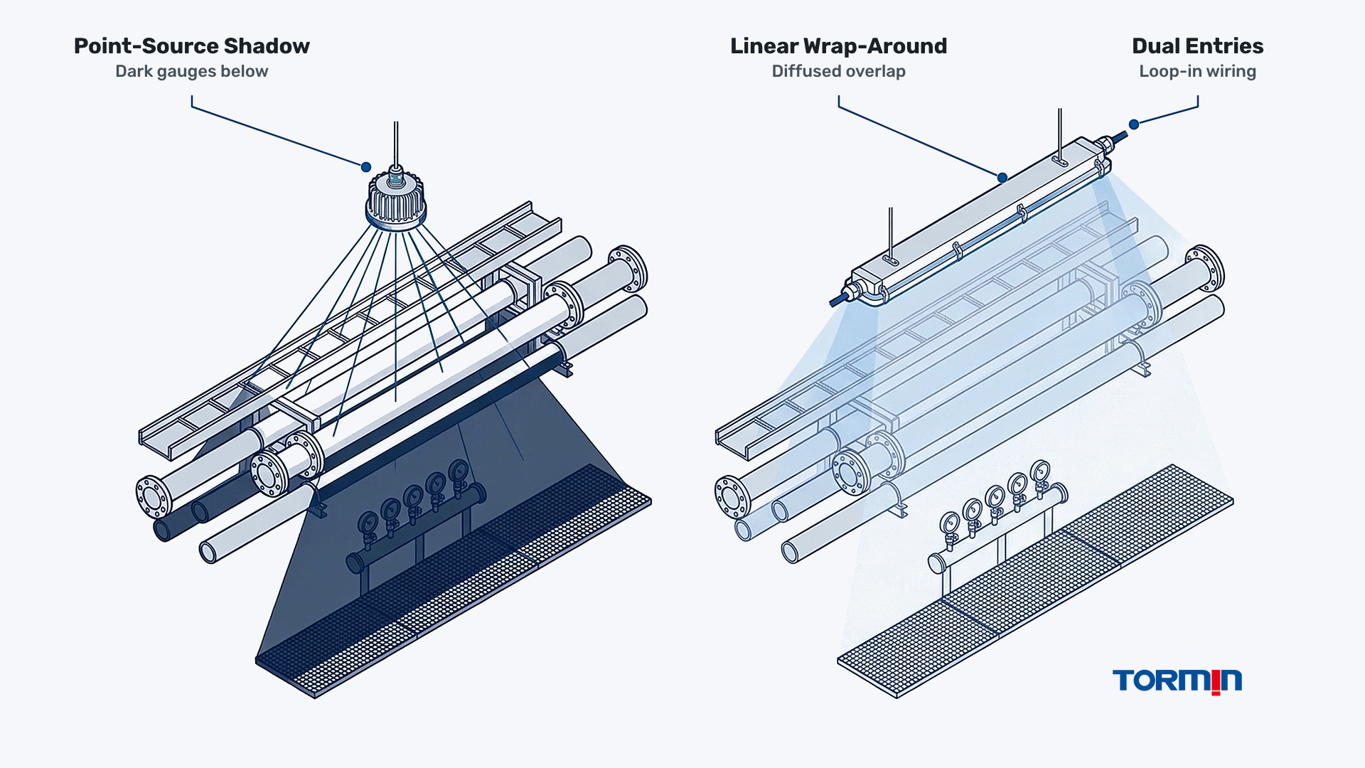
Wiring topology reinforces this divide. Along a 40 m process walkway or pipe gallery, linear luminaires designed with a separate terminal chamber and dual cable entries (for example, the TORMIN BC5402A linear family) allow qualified installers to loop power cleanly from fixture to fixture where permitted by the certificate and circuit load limit. High bays and mast-mounted floodlights typically use single-point feeds that rely on dedicated overhead explosion-proof junction and terminal boxes to split branch circuits. Keep all cable gland thread matching and unused-entry stopping plugs compliant with IEC 60079-14 installation rules and cable gland selection practices.
Thermal Fin Orientation, Aiming Angles, and T-Class Limits Under IEC 60079-0
Hazardous-area LED luminaires rely on passive natural convection across die-cast aluminum fins to stay below their certified maximum surface temperature (T-class) at the rated upper ambient temperature (Ta). Changing a luminaire’s mounting orientation or aiming tilt changes how hot air rises off the heat sink, which directly affects LED driver reliability and explosive-atmosphere safety margins.
Under IEC 60079-0, temperature classification testing is performed in the worst-case mounting orientation declared by the manufacturer and recorded in the certificate and installation manual. Round radial-fin high bays are engineered primarily for vertical downward pendant or ceiling mounting so heated air drafts unobstructed upward through the fin channels. Mounting a high bay sideways on a wall bracket—or tilting a high-power modular floodlight close to horizontal with fins facing downward—can trap warm boundary-layer air and raise housing or driver temperatures above the tested envelope.
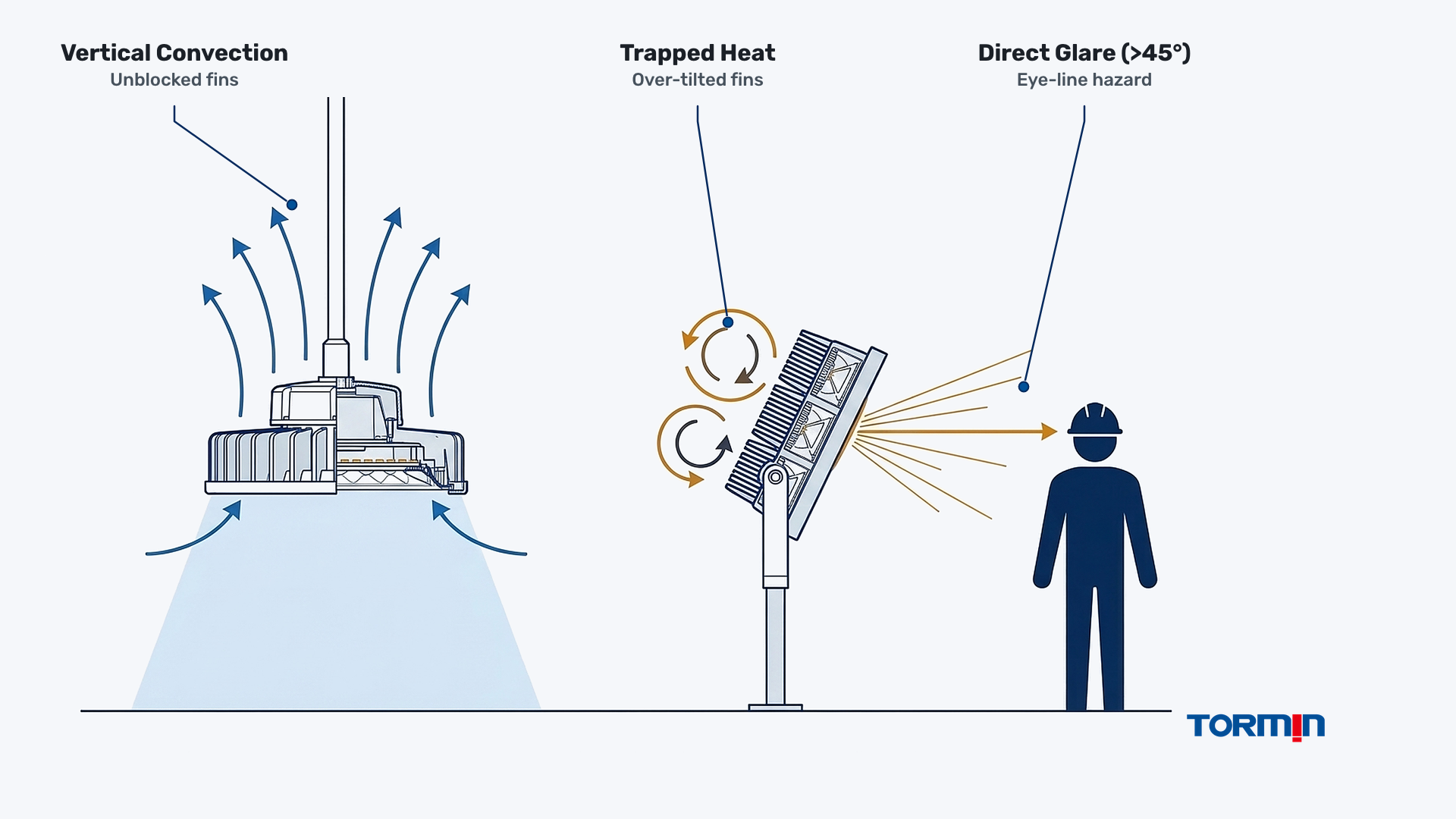
Outdoor explosion-proof LED floodlights—such as the modular bracket-mounted TORMIN BC9102S (60 to 300 W)—must also balance aiming angle against glare and spill. Aiming a symmetrical floodlight higher than 45 to 60 deg from vertical nadir throws intense direct glare into the eyes of crane operators, truck drivers, and security cameras while delivering poor horizontal illuminance on distant ground planes. Where long horizontal throw is required, specify dedicated asymmetric optics or higher mast heights rather than cranking a wide symmetric floodlight upward. For deeper aiming mechanics and ambient thermal checks, review our guides on industrial LED floodlight aiming, gas groups and temperature classes, and the Ambient Temperature Derating Checker.
Zone-by-Zone Plant Mapping: Matching Hazardous Facility Areas to the Right Form Factor
Most industrial facilities require all three luminaire form factors working together rather than a single universal fixture type. Mapping each plant area by ceiling height, obstruction density, and maintenance access prevents over-specification in low walkways and under-lighting in open process bays.
| Plant Area / Process Zone | Typical Height (m) | Dominant Constraint | Recommended Primary Form Factor | Backup / Hybrid Arrangement |
|---|---|---|---|---|
| Multi-tier refinery pipe rack & walkway | 2.5 to 4.5 m | Dense overhead piping, low headroom, shadow control | Explosion-proof linear luminaire | Compact wide-beam bulkhead at stairwells |
| Compressor hall or chemical reactor bay | 8.0 to 14.0 m | High ceiling, overhead crane clearance, fixture count | Explosion-proof high bay luminaire | Add linear under-mezzanine task lighting |
| Outdoor tank farm & bund perimeter | 10.0 to 20.0 m | No overhead roof structure; pole/mast perimeter mounting | Explosion-proof floodlight (aimed <= 45 deg) | Linear fixtures on local tank-side stair platforms |
| Truck & rail loading rack canopy | 4.5 to 7.0 m | Vehicle clearance, operator glare, vapor release near hatch | Explosion-proof linear or low-glare wide high bay | Floodlights only on exterior approach lanes |
| Paint booth or pharmaceutical cleanroom | 3.0 to 5.0 m | Flush/sealed cleanability, solvent vapor or dust layers | Sealed linear or explosion-proof cleanroom panel | Avoid finned high bays that trap overspray/dust |
| Offshore deck module & jetty walkway | 3.0 to 6.0 m | Salt-spray corrosion, vibration, low overhead structure | Marine-grade linear (e.g., 316 stainless hardware option) | Corrosion-resistant floodlights for open laydown deck |
Confirm area classification boundaries (Zone 1 vs Zone 2, Zone 21 vs Zone 22, or applicable NEC Division boundaries) from the site hazardous-area drawing before finalizing fixture models; see how to determine area classification and our complete explosion-proof lighting selection guide for the upstream compliance sequence.
Photometric and Engineering Input Checklist Before Requesting a Quotation
Submitting wattage targets alone forces hazardous-area lighting suppliers to guess ceiling elevations, beam optics, and obstruction density, producing incomparable quotations. Provide the five structured engineering input categories below when requesting IES or LDT photometric files, model-specific ATEX or IECEx certificate schedules, and project pricing.
| Input Category | Exact Parameters to Include in Your Enquiry | Why It Changes Form-Factor Selection |
|---|---|---|
| Area Classification & Compliance | Zone or Division, gas/dust group (IIA/IIB/IIC or IIIA/IIIB/IIIC), required T-class, required certificate scheme | Filters eligible protection concepts (Ex d vs Ex e) and certified mounting orientations |
| Spatial Geometry | Room or yard length and width (m), clear mounting height (m), crane rail or pipe-rack elevations (m) | Sets high bay vs linear vs floodlight elevation boundaries and obstruction height |
| Illuminance & Visual Task | Target maintained illuminance (lx), uniformity ratio (Uo), vertical vs horizontal task plane | Determines optic beam angle and whether asymmetric floodlight optics are required |
| Thermal & Environmental Conditions | Minimum and maximum ambient temperature Ta (°C), coastal salt spray, chemical vapors, washdown IP rating | Governs heat-sink derating, 304 vs 316 stainless hardware, and housing finish |
| Electrical & Mounting Infrastructure | Supply voltage (VAC or VDC), frequency (Hz), preferred entry thread (M20, M25, NPT), pendant vs bracket vs pole | Confirms whether loop-in linear chambers or overhead Ex junction boxes are needed |
When your layout inputs are ready, send the site drawing, hazardous-area schedule, and target illuminance requirements to [email protected] or via the TORMIN Contact page to request matching IES/LDT photometric files and model-specific certificate schedules across our explosion-proof high bay, explosion-proof linear, and explosion-proof floodlight families.
Sources
- IEC 60079-0 — Explosive atmospheres: Equipment general requirements
- IEC 60079-14 — Explosive atmospheres: Electrical installations design, selection and erection
- IEC 60079-17 — Explosive atmospheres: Electrical installations inspection and maintenance
- ISO 8995-1 / CIE S 008 — Lighting of work places, Part 1: Indoor (aligned with EN 12464-1)
- ISO 8995-3 / CIE S 016 — Lighting of work places, Part 3: Lighting requirements for safety and security of outdoor work places (aligned with EN 12464-2)
- IES LM-63 — Approved Method: IES Standard File Format for the Electronic Transfer of Photometric Data
- TORMIN Standards and Certifications Archive (first-party product documentation)