
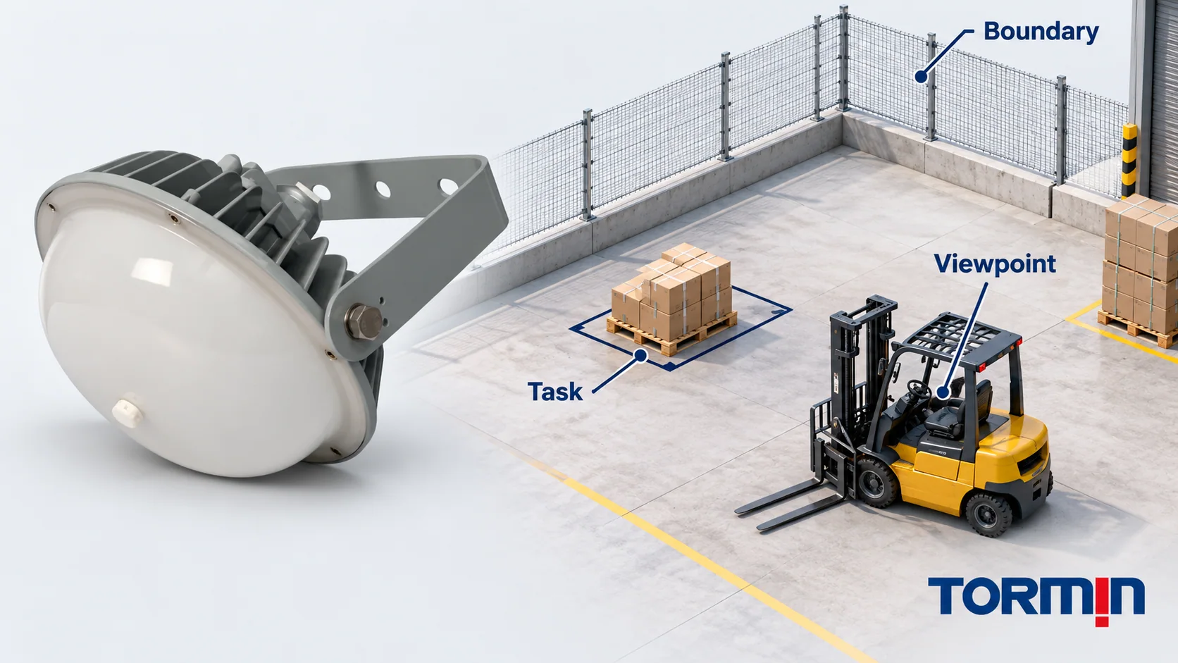
Industrial LED floodlight aiming should align the verified light distribution with the work, then check the same arrangement from observer positions and beyond the target area. Aiming at the far edge of a yard is a geometric choice; it does not establish useful coverage, acceptable glare or controlled spill.
The practical outcome is a repeatable design proposal: identified luminaires and optics, mounting coordinates, aiming targets, relevant viewpoints and receiver locations, with results checked against the project’s criteria. There is no single aiming angle that guarantees all of those outcomes.
Treat coverage, glare and spill as different questions
For this review, coverage means whether the required task surfaces receive the specified lighting across their usable extent. A loading apron, a vertical equipment face and a pedestrian route are separate targets. Define their criteria and evaluation planes before comparing arrangements.
Glare concerns the person looking into the scene. CIE’s International Lighting Vocabulary definition of glare describes visual discomfort or reduced ability to see details associated with unsuitable luminance distributions or contrasts. A ground-plane illuminance result alone cannot answer that observer question.
Here, spill refers to light reaching locations outside the intended task area. Mark the relevant receivers, such as a neighboring window or a location across the site boundary. Their requirements may differ from those of a worker inside the yard. CIE 150:2017 addresses assessment of obtrusive outdoor lighting and recommended limits. Obtain the applicable project and local requirements; this article does not reproduce the report’s numerical limits or establish legal compliance.
An aiming proposal therefore needs three views of the same design:
| Question | Place to evaluate | Information the reviewer needs |
|---|---|---|
| Does the lighting serve the work? | Defined horizontal, vertical or other task surfaces | Required lighting criteria, calculation points and relevant obstructions |
| What does the observer see? | Pedestrian, driver and operator positions with viewing directions | Appropriate glare assessment and the proposed installed orientation |
| Where else does light reach? | Defined boundary and off-site receiver locations | Applicable obtrusive-light criteria and operating conditions |
Do not replace this comparison with a photograph of a bright yard. A rendered picture can help communicate a design, but the proposal still needs its inputs and assessment results.
Map the target, viewpoint and receiver before choosing an aim
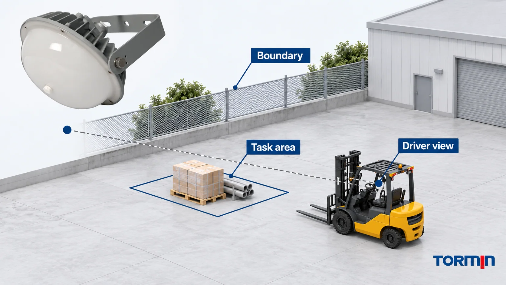
On the site plan and elevations, identify the tasks and the positions from which people perform them. Include the usual approach to a loading area, the direction a vehicle operator faces and any elevated workstation. Locate walls, stored equipment and other relevant obstructions.
Then mark the receivers outside the task area. The property line may be a reference, while an affected window or neighboring route is a separate evaluation location. Have the designer define the points and quantities needed by the applicable assessment method.
DarkSky and the Illuminating Engineering Society’s Five Principles for Responsible Outdoor Lighting support purposeful, targeted lighting, including shielding and careful aiming to keep light where it is needed. This is a design principle, not approval of a particular TORMIN product or a substitute for a calculation.
For a proposed floodlight position, draw a line to the intended target point. Keep it distinct from the observer’s viewing direction and the boundary. This makes the competing relationships visible before anyone calls an arrangement “good” or “bad.”
Separate the aiming direction from the optical distribution
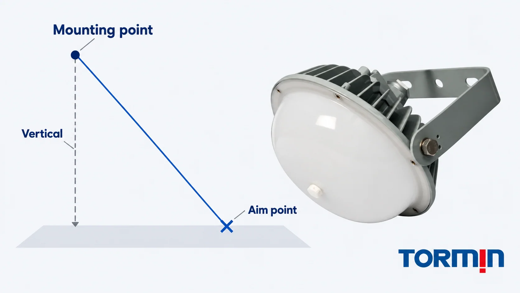
An aiming point defines a direction. The photometric file describes luminous intensity around its reference axes. Establish how those axes map to the physical fixture and its installed orientation.
Lighting Analysts’ AGi32 aiming guidance distinguishes global and luminaire-local axes and warns that a mistaken photometric zero plane can invalidate calculations. Confirm the mapping before comparing aims. The IES photometric-file guide covers file identity and reading separately.
Record the angle reference and rotation direction. “Tilt 40°” is ambiguous: downward vertical, below horizontal and a software rotation field need not mean the same thing. Obtain the manufacturer’s orientation information.
AGi32 also notes that software positions can exceed conventional hardware possibilities. Verify the offered bracket and attachment’s permitted arrangements against the exact product instructions before accepting the modeled orientation.
Worked example: calculate a target direction, not a universal tilt
The following is invented geometry for explanation, not a TORMIN layout, photometric calculation or bracket setting. Assume:
- a chosen luminaire reference point is 10 m above ground;
- the aiming target is 1 m above ground;
- the horizontal distance from directly below the luminaire to the target is 12 m.
The vertical drop is 10 − 1 = 9 m. In the vertical section containing both points:
Angle from downward vertical = arctan(horizontal distance / vertical drop)
                            = arctan(12 / 9)
                            = 53.1°

Angle below horizontal      = arctan(vertical drop / horizontal distance)
                            = arctan(9 / 12)
                            = 36.9°

Straight-line distance      = √(12² + 9²) = 15 m
Both angles describe the same line, using different references. The plan-view direction must also be specified to locate the target in three dimensions.
These numbers do not establish a 53.1° bracket adjustment, a particular direction of maximum intensity, or illuminance at the target. Those require the geometry-to-photometry mapping, permitted hardware arrangement and calculation inputs. If the target moves farther away while the vertical drop stays the same, this line becomes closer to horizontal. Whether that change puts more light toward a driver or an off-site receiver depends on the actual distribution.
The beam coverage calculator answers a narrower geometry question for a circular beam perpendicular to a plane. Its nominal footprint should not be used as the coverage boundary for this tilted arrangement.
Compare alternatives with the same task and receiver criteria
Start with one documented baseline. Identify the exact optic and photometric file, luminaire positions, orientation convention, output setting, relevant scene geometry and operating condition. Then change a defined variable and recalculate. Keep the comparison criteria consistent so the reviewer can see the tradeoff.
| Proposed change | Question it tests | Results to review together |
|---|---|---|
| Move the aiming target closer while retaining the same position and optic | Can a different direction serve the task with a different observer/receiver relationship? | Near and far task results, observer assessment and off-target results |
| Retain the target but change the mounting position | Does a new geometric relationship offer a better proposal? | All three assessments, plus the new mechanical and access constraints |
| Evaluate a different documented distribution | Can optical control address a limitation that aiming alone leaves unresolved? | Task coverage and uniformity, observer assessment, receiver results and exact optic identity |
| Evaluate a manufacturer-supported shield arrangement | Is a documented accessory configuration appropriate for the problem? | Compatible assembly, relevant photometric evidence, task results and off-target assessment |
None of these changes is automatically an improvement. A comparison needs to show what happens to the work as well as to unwanted light. Specify what was held constant, what changed and which conclusion the results actually support.
For example, consider a fictional loading-apron review. Scheme A aims toward the far task area. Scheme B keeps the same proposed optic and mounting position but moves the target nearer. If a submitted report presents only a lower value at one boundary point for Scheme B, it has not completed the comparison. Request its far-task results, relevant observer assessment and the remaining receiver results before choosing it.
If Scheme B meets one requirement but misses another, record that conflict. Consider a different distribution or location through a new documented comparison. Repeatedly changing the aim without preserving the other inputs makes it harder to explain why a proposal succeeds or fails.
Know when aiming alone is insufficient
When the available arrangements do not satisfy the combined criteria, revisit the design rather than treating an angle as the missing answer. The next study may involve another distribution, mounting position, supported shielding configuration or operating arrangement. Each change needs the corresponding product evidence and reassessment.
Avoid three shortcuts: treating the nominal beam angle as a hard cutoff; assuming an “anti-glare” product description settles every observer position; or assuming reduced light at one boundary point proves the whole proposal acceptable. Keep the conclusion tied to the evaluated configuration and locations.
For TORMIN candidates, the industrial floodlight and spotlight range provides product starting points. The ZY8601S LED Area Light supplies the real exterior reference used in this article. Its appearance does not establish a distribution, permitted aiming range, shield compatibility or site performance. Request the exact offered configuration and its supporting documents.
Hand over a reproducible aiming proposal
A useful aiming schedule connects each fixture ID to its model and optic, mounting coordinate, target coordinate or fully defined orientation, photometric-file reference and applicable mechanical restrictions. Attach the task, observer and receiver assessment results for the selected arrangement, with the criteria and operating conditions used.
If the decision remains open, state the unresolved comparison clearly. For example: “Compare the two target directions using the same offered optic, and report the task results, driver-view assessment and defined off-site receiver results.” Send the drawing, candidate model and that question through Contact TORMIN.
Any physical installation or adjustment must follow the exact manufacturer’s instructions and the responsible site’s authorized work arrangements. This article provides a design-review method, not a field-adjustment procedure.
Sources
- CIE — International Lighting Vocabulary, term 17-22-098: glare, 2020 — Visual discomfort and visibility implications of unsuitable luminance distributions or contrasts.
- CIE — Guide on the Limitation of the Effects of Obtrusive Light from Outdoor Lighting Installations, 2nd Edition, CIE 150:2017, public summary — Scope of obtrusive-light assessment; the licensed report’s numerical limits are not reproduced or claimed as reviewed.
- DarkSky International and IES — Five Principles for Responsible Outdoor Lighting — Purposeful, targeted light and the role of shielding and careful aiming. General design principles, not product certification.
- Lighting Analysts — AGi32: Aiming Parameters—Concepts — Photometric axes, orientation and the distinction between software positions and mounting-hardware possibilities. Software documentation, not a TORMIN installation instruction.
- TORMIN — ZY8601S LED Area Light — First-party product identity and exterior reference, reviewed 26 October 2026; no site photometric or aiming-performance claim is derived from the photograph.