
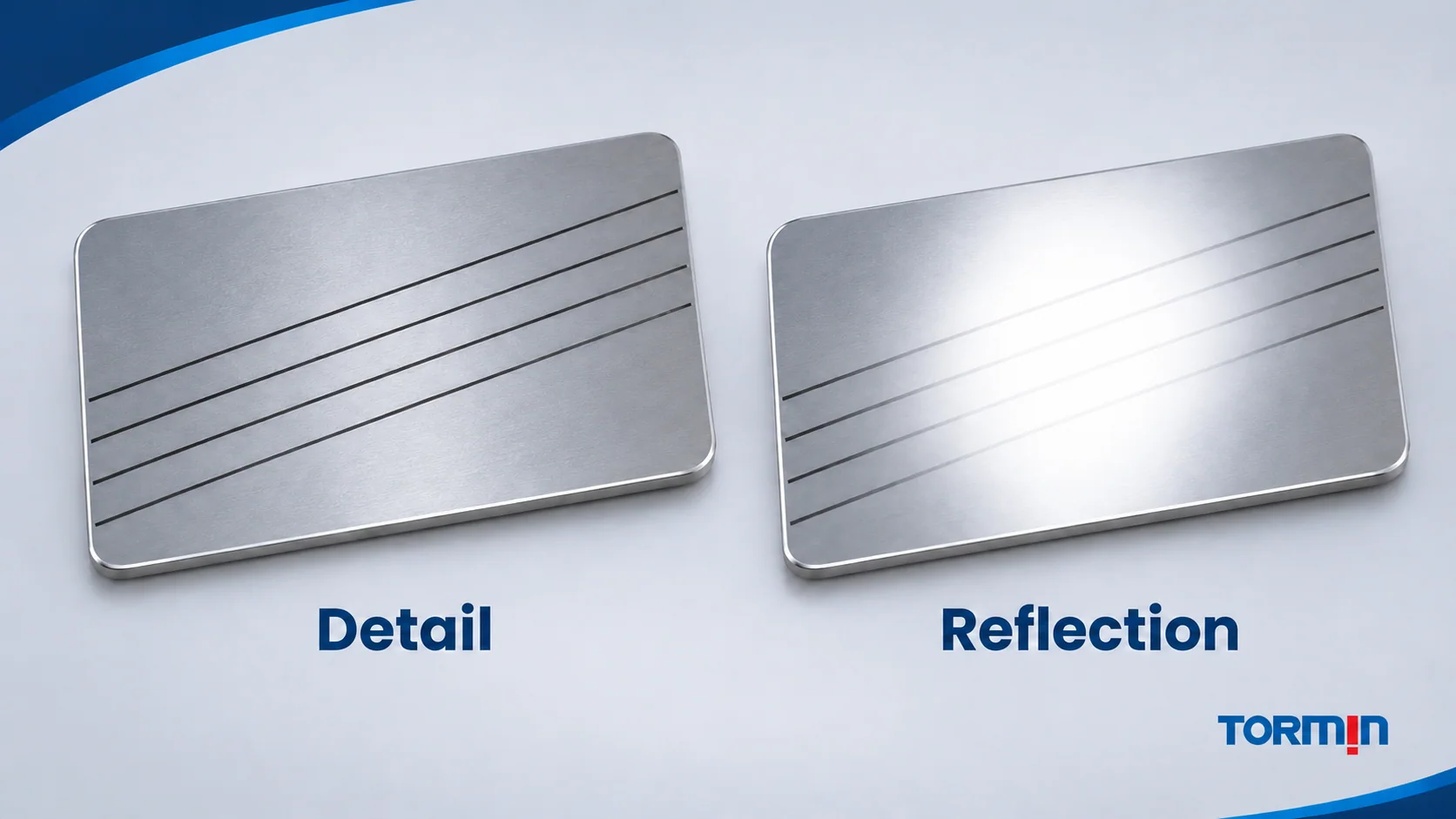
When a bright reflection covers the detail a worker needs to see, the source–surface–viewer relationship deserves attention alongside illuminance. Adding light can leave the reflection in place. The useful question is whether the required marks, edges or characters remain distinguishable from the normal working positions.
CIE uses glare by reflection for glare produced by reflections and marks the familiar term reflected glare as deprecated. Its definition of veiling reflection identifies the particular problem explored here: a specular reflection on the viewed object reduces contrast and obscures detail. CIE: glare by reflection; CIE: veiling reflection.
For an industrial assembly station, that might mean a bright source image washing across a glossy identification label. This article explains the mechanism and uses a fictional task trial to show how to compare arrangements without claiming that one luminaire, angle or lux value solves every reflective task.
Separate the light arriving from the detail being seen
Illuminance concerns light arriving at a surface. Reading a mark depends on the light reaching the eye from the mark and its surroundings. A surface can receive substantial light while a reflected bright patch makes its markings difficult to distinguish.
CCOHS distinguishes direct glare from glare caused by reflective surfaces. With direct glare, the bright source itself is in the person’s view. With glare by reflection, the surface returns a bright image toward the viewer. Screening a direct view of a luminaire does not necessarily remove its image from a glossy workpiece.
In a veiling reflection, the unwanted reflected image overlaps the task. Imagine dark characters on a pale glossy label: a bright reflection across both can make their difference harder to see. Increasing light output without changing this relationship does not establish that character visibility will improve.
The effect is about a particular view. A colleague standing beside the operator may see the reflection in a different place—or miss the problem entirely. HSE’s Lighting at Work describes bright reflections that overlay task detail and assesses them from the worker’s viewing position. It treats reflections beside a task and reflections masking the task as distinct review issues. HSE HSG38, paragraph 30 and the lighting-hazards table.
Why source, surface and eye position work together
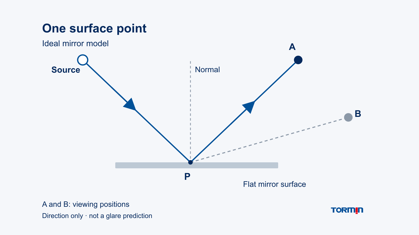
A simple mirror model explains the directional relationship. For an ideal smooth, flat reflecting surface, the incident and reflected rays make equal angles with the surface normal—the line perpendicular to the surface. Rougher surfaces spread reflection over more directions. OpenStax, University Physics Volume 3, section 1.2.
In the diagram, a generic point source sends one ray to surface point P. Its ideal reflection reaches viewing position A. Position B is outside that ray from P. This explains why one view can include a source reflection at a particular detail while another does not.
The model establishes direction, not reflection strength or visual acceptability. It also does not show that B is free of glare: another point on an extended surface, another source or a curved part could produce a different reflection. Real luminous areas and real finishes are more complex than a point source and perfect mirror.
For a real task, retain the source positions and apparent sizes, the surface finish and orientation, and the range of normal eye positions. Record whether windows or other bright surfaces contribute. A change in part orientation or working posture can move the reflected image relative to the detail even when the luminaire stays fixed.
A fictional assembly-task comparison
Fictional teaching case—not a project report or product test. An operator must read the complete identifier on a glossy, static component in an assembly fixture. Three normal viewing positions are agreed for this invented evaluation. They are the task’s required views; they are separate from positions A and B in the ideal-mirror diagram.
Assume that the same component, identifier, fixture and viewing distances are used throughout. Source output is held constant except for the explicitly increased output in Alternative C. Assume the separate task-illuminance criterion remains satisfied in each arrangement. No numeric target or real lighting calculation is supplied.
The trial criterion is simple: the complete identifier must be distinguishable at each of the three agreed views without the operator adopting a compensating posture. The following observations are invented to teach interpretation:
| Arrangement | Invented observation | Decision for this reading criterion |
|---|---|---|
| Original arrangement | A reflected bright patch covers the identifier’s centre in one required view | Does not satisfy the criterion |
| Alternative B: source position changed in the mock-up | The patch lies away from the identifier, and all characters remain distinguishable in all three views | Satisfies the stated reading criterion |
| Alternative C: original arrangement with increased output | The patch remains over the identifier and the central characters remain difficult to distinguish | Does not satisfy the criterion |
Alternative B wins this fictional reading comparison. The reason is the completed visual task across its required views, not the fact that a source was moved. Alternative C demonstrates why an increase in output is insufficient evidence of an improvement.
These observations do not predict the result of moving a real TORMIN product. They also do not assess a separate task such as detecting a surface scratch, reading another face or working in a different posture. Those require their own task evidence.
Choose the design change around the actual task
CCOHS identifies source positioning, suitable light distribution and lower-gloss surfaces as possible approaches to glare problems. It also retains the need for appropriate general lighting. These are options to evaluate, rather than interchangeable fixes. CCOHS: Lighting Ergonomics—Survey and Solutions, glare sections.
Changing the spatial relationship may move a source image away from the required detail. Review the full working range afterward: a change that helps a seated view can create a reflection from a standing view or cast a new shadow. Workers should not have to maintain an awkward posture to make the lighting usable.
Changing source appearance or distribution can change the reflected pattern. A broader luminous area may produce a broader reflection, so “diffused” alone is not proof of better reading. Compare the actual configuration with the representative surface. Any optical accessory needs manufacturer approval for the exact equipment; do not improvise a cover or attach a film to an installed luminaire.
Changing an incidental surface finish can help where the surface is simply a workbench or reading aid. A manufactured part is different: its gloss, coating or texture may be a controlled product characteristic. Altering it would change the task being assessed. Improve the lighting and viewing arrangement around that part instead of treating its finish as freely adjustable.
Likewise, a bright reflection is not automatically unwanted. If the inspection task depends on seeing a reflected pattern or a finish change, the acceptance question must name that feature. A successful identifier-reading arrangement cannot be assumed suitable for every surface-inspection task.
Keep the visibility result and the lighting evidence together
For a representative task review, retain the sample and finish, the detail to be seen, the agreed eye positions, the part orientation and the lighting configuration. Describe what was visible in each arrangement. Include the relevant ambient-light conditions so that a demonstration made under one window condition is not silently treated as evidence for another.
Keep illuminance evidence alongside those observations. A task that is readable but fails the applicable lighting requirement still needs review. Conversely, an acceptable average-lux result does not settle the contrast question. TORMIN’s uniformity guide addresses a separate spatial check, while the IES-file guide explains the distribution data used in a calculation. Neither replaces the source–surface–eye review.
The ZY8607P product page supplies the first-party exterior reference used on this article’s cover. It is not assigned a glare rating or a result from the fictional trial. The industrial high-bay category provides a route to candidate families once the project requirements are known.
For a project discussion, include the actual reflective sample or a useful description of its finish, the viewing range and the detail that must remain visible. The intended outcome is a reviewable arrangement that supports that task under its stated conditions.
Sources
- CIE—International Lighting Vocabulary, glare by reflection, 17-22-100 (2020)—definition and terminology status.
- CIE—International Lighting Vocabulary, veiling reflection, 17-22-101 (2020)—reflection over an object reducing task contrast.
- CCOHS—Lighting Ergonomics: Survey and Solutions—glare causes and design options; no numeric criteria imported here.
- HSE—Lighting at Work, HSG38, second edition (1997)—paragraph 30 and the hazards table on viewing-position and task-reflection assessment; historical UK guidance, not a product approval.
- OpenStax—University Physics Volume 3, section 1.2, The Law of Reflection—ideal reflection direction and smooth/rough surface distinction.
- TORMIN—ZY8607P LED High Bay Light—first-party product identity and exterior only.