
Short answer
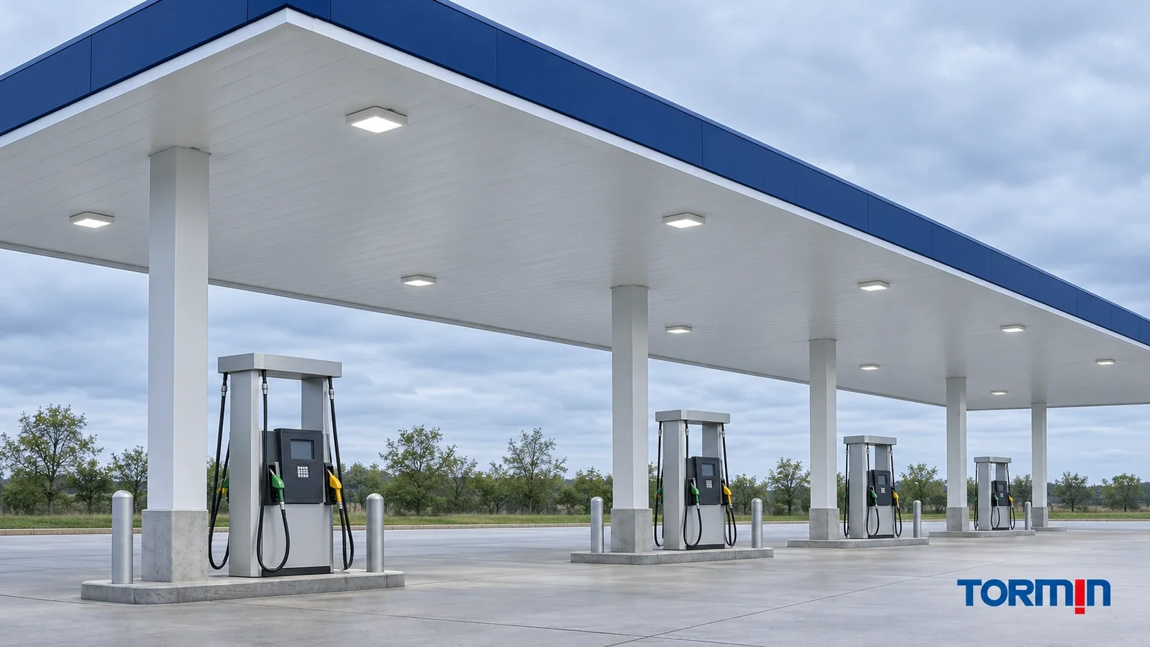
Usually, no. At an outdoor gasoline station with ground-mounted dispensers, the broad dispenser-related Class I, Division 2 layer rises only 450 mm (18 in.) above grade. A canopy ceiling light that sits above that layer and outside every other applicable classified volume normally needs no hazardous-location rating for its position. Specify a luminaire suitable for wet locations where it is exposed to water, and check the wiring route separately. A nearby vent outlet or a fixture mounted beside a dispenser can change the answer. [1, 2]
This guide covers an ordinary outdoor gasoline forecourt with underground storage. Use the approved site classification plan and elevations to locate each item, including the luminaire housing, its connections and the supply route. Confirm the edition adopted for the project and the authority having jurisdiction (AHJ). Gaseous fuels and other dispensing arrangements have separate rules.
| Position | Classification in this example | Lighting decision |
|---|---|---|
| Canopy soffit fixture above the 450 mm (18 in.) slab and clear of all other envelopes | Unclassified at the fixture | Hazardous-location identification is ordinarily unnecessary for this position. Verify wet or damp exposure and above-area wiring. |
| At grade to 450 mm (18 in.) above it, within 6.0 m (20 ft) horizontally of the dispenser enclosure | Class I, Division 2 | Evaluate the light for that classified location. |
| Beside the dispenser enclosure or its liquid-handling portion, within 450 mm (18 in.) horizontally, extending down to grade | Class I, Division 2 | Check low or side-mounted fixtures against this separate volume. |
| Within or under the dispenser pit or containment | Class I, Division 1 | Specify suitable Division 1 equipment if lighting is needed there. |
| Near an underground tank vent outlet | Division 1 within 1.5 m (5 ft). Division 2 in the surrounding shell out to 3.0 m (10 ft). | Use the outlet and fixture elevations as well as the plan distance. |
| At an underground tank fill opening | Division 2 from grade to 450 mm (18 in.), within 1.5 m (5 ft) of tight-fill or 3.0 m (10 ft) of loose-fill. An applicable intersecting belowgrade pit or box is Division 1. | Check the fill arrangement, the fixture position and any belowgrade space separately. |
The table uses selected rows of NEC Table 514.3(B)(1) in the verified 2020 NEC-based text and cross-checks them against NFPA 30A (2024), Table 8.3.3. The final classification also depends on the facility arrangement and adopted edition. The general area-classification guide explains how to read the project record. [1, 2]
The classified box around a dispenser
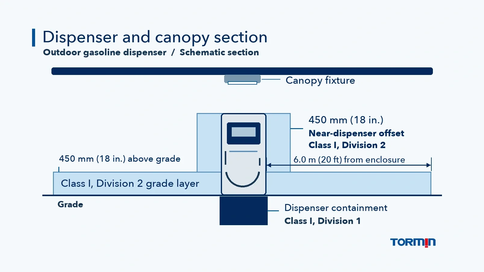
Look at the side elevation of the dispenser. NEC Article 514 assigns volumes around sources and equipment features. For this arrangement, the drawing needs to distinguish three adjoining areas. Gasoline vapor is heavier than air and can collect in low spaces, which helps explain the shallow grade-level layer and the particular treatment of pits. Apply the code dimensions even when a site appears well ventilated. [1, 2, 3]
The below-dispenser space. The table assigns Class I, Division 1 to the space within and under the dispenser pit or containment. That row addresses the containment space. The note for the ordinary dispenser directs the classification inside its enclosure to UL 87 and the dispenser listing. Use the listed assembly’s documents for internal equipment and service parts. [1, 2]
The near-dispenser envelope. Class I, Division 2 extends 450 mm (18 in.) horizontally from the dispenser enclosure or its liquid-handling portion, in all directions and down to grade. Its upper extent follows the relevant enclosure portion. A light can therefore be above the shallow ground layer and still sit within the volume beside the dispenser. Locate the applicable enclosure face on the drawing before taking the offset. [1, 2]
The outdoor grade layer. A separate Class I, Division 2 layer reaches 450 mm (18 in.) above grade and extends 6.0 m (20 ft) horizontally from the dispenser enclosure in all directions. The distance starts at the enclosure. Measure it independently of the edge of the pump island, the canopy column or a painted traffic line. Where several dispensers are present, check the point against each applicable outline. [1, 2]
A plan view shows the horizontal reach. The section through the actual fixture shows which height interval it occupies. Use both views when the installation appears directly above or alongside the boundary. The Class I, Division 1 and Division 2 lighting guide covers equipment selection after the division is established.
Why the canopy ceiling sits outside it
A canopy luminaire typically sits well above the 450 mm grade layer. Direct alignment with a dispenser in plan does not put it inside that shallow layer. Check its position against the taller, narrower envelope alongside the dispenser as well. If the entire fixture location clears those volumes and every other classified source on the site drawing, its elevation is unclassified. [1, 2]
Use the actual bottom of the installed assembly when comparing elevations. A flush fixture and a suspended fixture occupy different space. An outlet box, remote driver or service connection may also sit at a different elevation from the visible lamp. Assign each component to the space it occupies and record the locations together. This lets the reviewer distinguish a fixture position change from a wiring or equipment change.
For example, consider a proposed ceiling light shown directly over a pump on the plan. The section shows the complete fixture above both dispenser envelopes, and the vent drawing puts it clear of the outlet envelopes. The position needs ordinary location suitability and the applicable wiring review. Its location above the dispenser alone does not call for a hazardous-location listing under a standard such as UL 844. [1, 4] A separate accent light proposed on the same island, beside the liquid-handling portion of the dispenser, could fall inside Division 2. Those are two fixture decisions on one canopy schedule.
The open gasoline arrangement controls this conclusion. Confirm the fuel types and release sources on the project documents, especially where a canopy serves more than one fuel. Forecourts outside the US follow the rules applicable in their own jurisdiction.
What canopy fixtures still need
Match the environmental exposure
Use a luminaire marked suitable for wet locations where water can reach the installation. A fully sheltered position may be damp under the applicable definitions, in which case a suitable damp- or wet-location luminaire can be used. Consider the actual exposure to wind-driven rain and the way the fixture, box and connections will be installed. NEC 410.10(A) addresses both the luminaire marking and protection of electrical parts from water entry or accumulation. [1]
Verify the environmental suitability for the chosen mounting orientation and installation arrangement. The cut sheet for a fixture is useful evidence only when it describes the unit and installation being submitted. In a wet position, check the marking before approving the substitution. Check hazardous-location identification separately wherever the installation requires it.
Follow the circuit through the classified boundaries
Article 514 has requirements for fixed wiring and equipment above Class I locations. Check the adopted text of 514.7 for the above-area installation. Then trace the circuit from its source to the fixture. A run may rise through the near-grade layer, enter an enclosure on the island or pass beneath a classified location even when its load is high overhead. [1]
Article 501 applies to wiring and equipment in the classified space through 514.4, subject to the applicable provisions of Article 514. Check 514.8 for underground routing and 514.9 for dispenser and boundary sealing. Under the verified text, the boundary provisions refer to 501.15 and apply to horizontal as well as vertical boundaries. The route and its applicable provisions determine where seals are required. [1]
A conduit can provide a path for vapor migration into a connected enclosure. Show penetrations, transitions and enclosure entries on the route drawing so that the designer can identify the required sealing and prevent that path. A ceiling fixture schedule alone cannot document those conditions. For a proposed route, mark the point where it enters a classified volume, the point where it leaves, and any dispenser or containment connection. Give the reviewer both views if a riser crosses the top of the grade layer. Where a route stays entirely above the volumes, the above-location provisions still guide the wiring review. These checks can change the electrical scope even when the fixture model stays the same. Use the conduit-seal guide for the separate sealing review.
The forecourt lights that DO need a rating
Low bollard or wall fixtures. A fixture within 6.0 m (20 ft) horizontally of the dispenser enclosure and at or below 450 mm (18 in.) above grade falls in the outdoor Division 2 layer, subject to the actual classified limits on the project. A side-mounted fixture above that layer also needs a check against the near-dispenser envelope. Mark the whole installation position before comparing equipment. [1, 2]
Where the mounting position is Division 2, evaluate the proposed fixture against the applicable equipment rules. An ordinary weather rating answers the environmental exposure question. The general-purpose lighting guide covers equipment evidence for a position already classified as Division 2. For a perimeter floodlight, record the aiming and visibility requirements after establishing equipment suitability. See the floodlight aiming guide.
Fixtures near a vent outlet. A high wall light, pole head or canopy fixture can intersect a vent envelope. Locate the open end in the elevation, then compare the fixture to both the inner Division 1 space and the outer Division 2 shell. The plan alone can miss an outlet at the fixture’s level. [1, 2]
Pit lighting. A light inside Division 1 dispenser containment, or in a belowgrade pit or box classified by the fill-opening row, needs equipment suitable for that division. Confirm which pit the table applies to and where the equipment is actually installed. Avoid transferring the containment rule to unrelated underground spaces without checking their own conditions. [1, 2]
Indoor dispensing. Indoor dispensing follows separate rows, including a horizontal reach of 7.5 m (25 ft) for the gravity-ventilated arrangement in the verified table. [1, 2]
Vents and fill points: the envelopes people forget
Measure from the vent opening
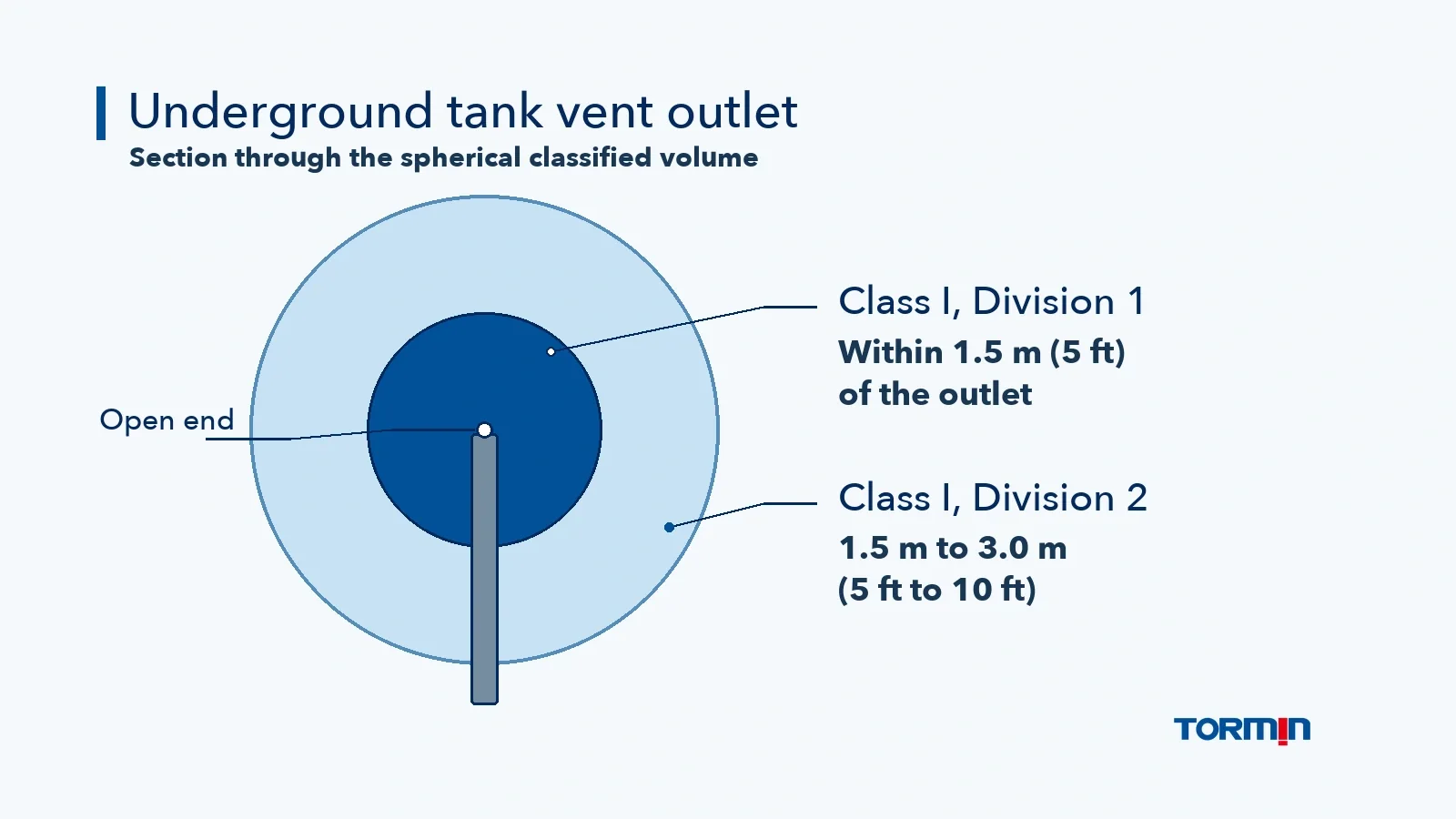
For the underground gasoline tank vent row, the open end is the center. The space within 1.5 m (5 ft) in every direction is Class I, Division 1. The surrounding volume from that inner boundary out to 3.0 m (10 ft) is Class I, Division 2. These are radial distances, so the classified space extends sideways, above and below the outlet. An upward-facing opening does not confine the envelope to the air directly above the pipe. [1, 2]
A wall light drawn well above grade can still be near that opening. Conversely, a pole base and the luminaire on the pole may occupy different classified spaces. Confirm the outlet point on the mechanical drawing and the luminaire on the electrical elevation. Compare their spatial relationship before assigning the equipment requirement. If the drawing omits the vent elevation, obtain it before deciding whether the adjacent canopy fixture is unclassified.
Identify the fill connection and belowgrade space
At an underground tank fill opening, Division 2 extends up to 450 mm (18 in.) above grade. Its horizontal reach from a tight-fill connection is 1.5 m (5 ft), and from a loose-fill connection it is 3.0 m (10 ft). Use the actual connection type in the project documents. The wider slab around a dispenser starts at the dispenser, while these dimensions start at the fill connection. A light clear of one may still be within the other. [1, 2]
The fill-opening row also addresses belowgrade pits or boxes. If any part of a qualifying belowgrade pit or box lies within the classified location described by that row, the entire space inside it is Division 1. Establish the pit geometry on the drawing. Record the pit as a separate volume on the elevation so the equipment schedule addresses everything installed in it. A service light mounted on the rim may occupy a different space from the box or lamp below. Where the connection type or pit extent is unclear, use the approved fill detail before assigning the lighting requirements. [1, 2]
Three mistakes
- Assigning Division 2 to the whole station. Carry the actual boundaries into the fixture schedule. This avoids specifying and paying for a hazardous-location construction where the approved fixture location and project requirements do not call for it.
- Reviewing only the high ceiling fixtures. Include low wall lights, bollards, pit lights and fixtures near vent openings. The same drawing review should identify where the supply crosses a boundary. That keeps the equipment decision and the route decision tied to their actual locations.
- Transferring an indoor range to an outdoor site. Select the applicable row for the dispensing arrangement and its ventilation. Confirm the edition adopted for the project and the AHJ. Use the current approved site classification when making the final comparison.
FAQ
Do gas station canopy lights need to be explosion proof?
Usually not when the high-mounted fixture clears the 450 mm (18 in.) dispenser slab and every other applicable classified volume. Select wet-location suitability where the fixture is exposed to water, and verify the supply route separately. [1, 2]
How far does the Class I area extend around a fuel dispenser?
For the ordinary outdoor arrangement, the Division 2 slab reaches 6.0 m (20 ft) horizontally from the enclosure and 450 mm (18 in.) above grade. A separate Division 2 envelope extends 450 mm (18 in.) horizontally beside the relevant enclosure portion and down to grade. Under-dispenser containment is Division 1. Check the dispenser listing for the interior. [1, 2]
Which lights at a gas station DO need a hazardous-location rating?
Evaluate fixtures in the applicable classified volumes. These include low lights in the dispenser or fill layers, lights intersecting the vent envelopes and lights in qualifying Division 1 pits. The division at each position sets the equipment review. [1, 2]
Does the wiring above the canopy need seals?
Follow the entire route. Review Article 501 and NEC 514.9 where the run crosses a defined boundary or serves the dispenser and connected cavities. Check the underground and above-area provisions where applicable. A high fixture location alone does not determine the seal locations. [1]
Is a whole gas station a Class I, Division 2 location?
Classification follows the applicable source volumes and site conditions. The outdoor dispenser, tank vent, fill point and containment can have different extents or divisions. Use the approved plan and elevations for the position being evaluated. [1, 2]
Sources
- California Building Standards Commission — 2022 California Electrical Code, based on the 2020 NEC. Article 100 location definitions, 410.10(A), Article 501, 511.7 and Article 514, including Table 514.3(B)(1) and 514.4, 514.7, 514.8 and 514.9. Check the edition adopted for the project and the AHJ.
- NFPA — NFPA 30A, Code for Motor Fuel Dispensing Facilities and Repair Garages. The comparison here uses the 2024 edition, Table 8.3.3, including the dispenser, fill opening and underground tank vent rows.
- CDC/ATSDR — Gasoline, Automotive: Medical Management Guidelines. Gasoline vapor can collect in low-lying spaces.
- OSHA — UL scope of NRTL recognition. Identifies UL 844 as a standard for luminaires in hazardous classified locations.