
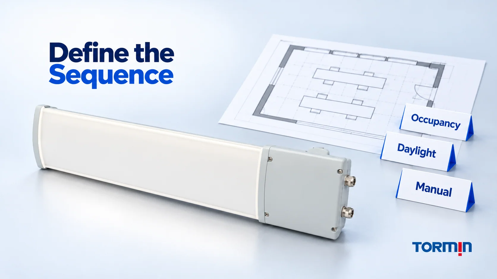
An industrial lighting control sequence should state which input takes priority, what lighting response is requested and how that request ends. “Occupancy sensors plus daylight dimming” names features, but leaves their interaction unresolved. A useful sequence tells the design team what should happen when someone enters, daylight changes, a manual hold is active or two timers expire together.
PNNL’s Selecting Lighting Control Systems distinguishes general control intent from the detailed sequence needed for setup and commissioning. It also calls for the intended behavior to match the final selected system’s capabilities. A written request does not establish that the offered equipment can implement it.
The example below covers ordinary normal-operation task lighting. Emergency, egress, hazardous-area and safety-critical functions need their own applicable design basis. No wiring, live testing or controller programming procedure is provided.
Define the group, inputs and requested scenes
Start with a named group and a drawing reference. Identify the luminaires that belong to it, the task area it serves and the inputs permitted to affect it. A circuit number alone does not describe the intended control group. The existing warehouse lighting guide explains the wider task-area and layout context.
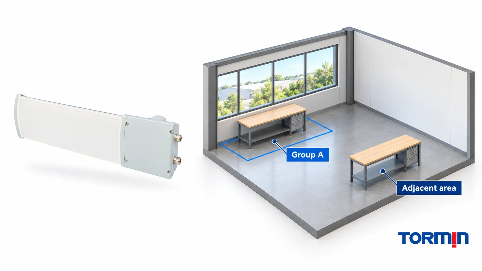
For the fictional example, Group A serves one hypothetical task area near a daylight opening. It has valid occupancy and daylight inputs and an available temporary manual-hold request. The example supplies no real site, sensor coverage, controller, driver, protocol or product configuration.
Three names describe the requested behavior:
- Occupied scene with daylight response: the agreed occupied-task behavior, using the agreed daylight response while that scene is requested.
- Manual scene: the agreed temporary behavior requested by the manual hold.
- Vacant scene: the agreed behavior after vacancy is confirmed and its delay has expired. This name does not mean “off.”
These are functional scene names, not device commands, dimming percentages or guaranteed illuminance. A real specification must define their criteria and implementation. The vacancy delay, hold duration, daylight settings and allowable output range remain project decisions; this example assigns no values to them.
Write the priority and release rules
Fictional normal-operation example — design intent only. The following rules are an original teaching model, not a TORMIN controller program or a prescribed site sequence.
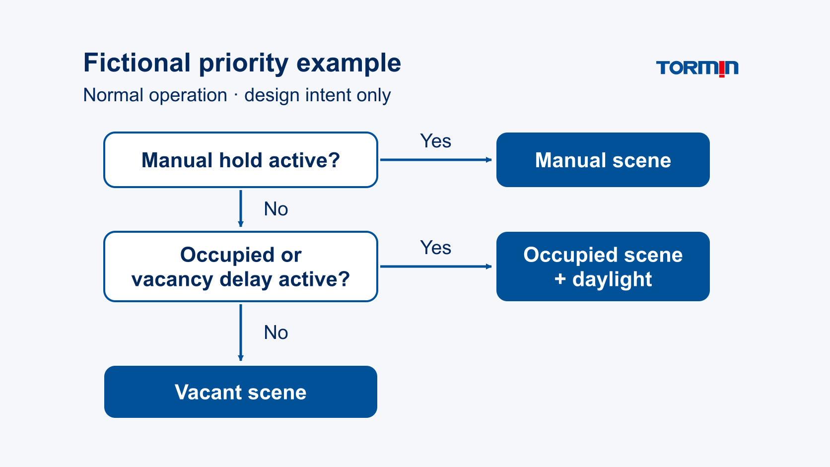
For Group A, evaluate these conditions in order:
- Manual hold active: request the manual scene. Automatic occupancy and daylight requests do not replace it while the hold remains active.
- No active hold, and occupied or vacancy delay still active: request the occupied scene with daylight response.
- No active hold, vacant and vacancy delay expired: request the vacant scene.
The vacancy timer starts on a valid occupied-to-vacant transition, is cancelled by reoccupation and continues in the background during a manual hold. The hold has its own defined release or expiry. When it ends, evaluate the current conditions instead of restoring a remembered lighting request.
That last distinction resolves an otherwise ambiguous conflict: if the space became vacant during a hold, the correct next request depends on whether the vacancy delay is still active when the hold ends.
Follow the fictional event sequence
Each row below is a requested normal-operation response. Nothing in the table demonstrates that a particular driver, sensor or control system supports it. No output, time, power or energy value is implied.
| Event and current condition | Requested response in this example | Release or next evaluation |
|---|---|---|
| Group A is occupied; no manual hold is active. | Occupied scene with daylight response. | Re-evaluate when relevant current inputs change. |
| Daylight changes while the group remains occupied and unheld. | Continue the occupied scene using its agreed daylight response. | Apply the documented response method; do not infer task illuminance from the input label. |
| The temporary manual hold is activated. | Manual scene takes priority. | Hold remains active until its agreed release or expiry. |
| A valid occupied-to-vacant transition occurs while the hold remains active. | Keep the manual scene; start the vacancy timer in the background. | The timer continues independently of the hold. |
| The hold ends while still vacant, before the vacancy delay expires. | Occupied scene with daylight response, evaluated using current conditions. | Request the vacant scene if the delay expires before reoccupation. |
| The vacancy delay expires while vacant and no hold is active. | Vacant scene. | Reoccupation triggers a fresh evaluation. |
| Occupancy returns with no active hold. | Cancel the vacancy timer and request the occupied scene with current daylight response. | Continue normal evaluation; do not restore a stale request. |
| Alternative to the earlier hold-release row: hold expiry and vacancy-delay expiry coincide while vacant. | Vacant scene directly: neither hold nor delay remains active. | Reoccupation triggers a fresh evaluation. |
The simultaneous-expiry row is a useful review test. A description that says only “return to automatic” does not settle which automatic state applies. Here, the stated priorities and timer rules produce a clear answer. Another project may choose a different permitted interaction, but it must document that choice and verify that the selected system implements it.
The fictional model assumes valid inputs during normal operation. An unavailable input, controller restart, loss or restoration of power, or conflicting external command requires a separately agreed response. This example supplies no fail-state prescription.
Check whether the exact equipment can implement the request
Review the functional sequence alongside the offered configuration. PNNL’s component guidance specifically identifies compatibility between luminaires, drivers and the controls system as something to document. A luminaire-family description or a familiar protocol name does not answer every configuration question.
Ask the supplier and controls designer to identify the exact luminaire ordering code, driver/interface, controller and sensor models, relevant hardware/software versions and applicable instructions. Obtain confirmation of the required scene behavior, grouping, timer interaction, manual release and restart behavior. Record any unsupported request as a design issue before treating the sequence as implementable.
For a DALI-based proposal, use the DALI Alliance product database to check the specific component record and matching identity/version information. The database distinguishes certified components from registered products and notes that luminaires are not listed there. A component record does not demonstrate this fictional sequence, a complete luminaire’s configuration or an assembled project’s performance. No TORMIN DALI certification or compatibility claim is made here.
GSA’s lighting guidance also distinguishes products designed for dimming from compatible dimming equipment and emphasizes commissioning and operating knowledge. Treat a successful document review as the basis for an agreed verification plan, rather than proof that the installed behavior already matches.
Keep the acceptance record tied to the sequence revision:
Group and drawing reference:
Sequence revision and exact offered configuration:
Observed condition or event:
Expected request under the approved sequence:
Observed response and supporting record:
Difference, responsible reviewer and disposition:
Include the interactions that can reveal a hidden mismatch: daylight changing during a hold, vacancy during a hold, release before timeout, simultaneous expiry and reoccupation. These are observation requirements for the responsible project team, not instructions to alter an operating installation.
Keep the energy claim separate from the sequence
The fictional sequence yields no energy-saving result. It specifies requested behavior without supplying input-power measurements, operating hours or a baseline. A dimming request is not a measurement of electrical input power.
The U.S. Department of Energy’s Uniform Methods Project lighting-controls protocol evaluates savings against a defined baseline and addresses controlled power, operating conditions and the need to avoid double-counting controls savings with a lighting retrofit. Its methods do not justify borrowing a general savings percentage for a new project.
For an actual claim, document the baseline and proposed input-power profiles, the operating/occupancy/daylight assumptions, control and standby consumption, measurement boundaries and comparable service. Identify adjustments for changed conditions. If the project lacks those data, retain the proposed sequence as design intent and leave the savings estimate unclaimed.
Output behavior still needs lighting assessment. Use the project’s task criteria and calculation basis; the uniformity article explains why an average-lux value alone cannot establish the spatial result. The broader lighting-specifications resource provides the related specification context.
Send a reviewable control requirement
Attach the group drawing, sequence revision and unresolved interaction questions to the proposed configuration. That gives the supplier a precise capability request and gives the design team a record of what remains to be confirmed.
The official TORMIN ZY5322B / ZY5322BJ product page supplies the first-party exterior reference used in this article’s illustrations. Its use here is limited to product identity and visible exterior; no particular variant’s control or emergency capability is assessed. None of the fictional sequence is attributed to the pictured product.
Contact TORMIN with the intended normal-operation sequence and exact proposed configuration to request the relevant current documents. Resolve compatibility and the verification basis before accepting the behavior or an energy claim.
Sources
- PNNL — Selecting Lighting Control Systems, PNNL-SA-180668, updated 21 November 2022 — control-intent/sequence documentation, alignment with selected-system capabilities and luminaire/driver/controls compatibility; printed pages 14–16 and 19.
- DALI Alliance — Product database — exact component identity/version and certification/registration scope; database guidance checked 2 November 2026, no TORMIN component record asserted.
- GSA — Lighting, updated 20 August 2026 — dimming compatibility, daylight-control commissioning and operating knowledge; federal-building guidance, not a universal industrial design approval.
- Stephen Carlson / NREL — Chapter 3: Commercial and Industrial Lighting Controls Evaluation Protocol, NREL/SR-7A40-68559, September 2017 — baseline-based savings evaluation and avoiding double counting with retrofit measures; no generic savings factor used.
- TORMIN — ZY5322B / ZY5322BJ Linear LED & Emergency Light — first-party shared-page identity and official exterior reference only; no exact-variant control, certification or emergency-performance claim assessed.