

An oil and gas lighting enquiry should begin with the approved area-classification drawing and a location-by-location task schedule. It should not begin with wattage, lumens or a request for “Zone 1 lights.” For every mounting point, the supplier and project team need the applicable hazardous-area framework, gas or dust properties, required equipment protection, ambient and corrosion exposure, supply and cable-entry details, mounting/access constraints, lighting criteria, emergency function and document requirements.
The result is not a product list. It is a traceable input package that lets the hazardous-area specialist, lighting designer and manufacturer check the same location without silently filling gaps with assumptions.
First rule: classification establishes the explosion-protection boundary; the task and geometry establish the lighting requirement; exact product documents establish whether a proposed ordering code can satisfy both.
Treat the facility as a set of different locations
“Oil and gas site” is not an area classification. A well pad, process module, compressor shelter, tank bund, loading rack, pipe rack, workshop and control room can present different release sources, obstructions, tasks, access limits and environmental exposure.
IEC 60079-10-1:2020 concerns classification of areas where flammable gas or vapour hazards may arise and describes an area as a three-dimensional region or space. In the United States, 29 CFR 1910.307 requires each room, section or area to be considered individually and requires documentation for hazardous locations.
Use the approved project classification—not a generic industry diagram—to complete this matrix:
| Location | Hazard inputs | Visual task inputs | Installation and access inputs |
|---|---|---|---|
| Wellhead or manifold | Release sources, classification extent, gas group, temperature basis | Valves, gauges, leak checks, access routes | Low structures, vibration, weather, isolation and vehicle interface |
| Process module or platform | Multiple release points, ventilation and adjacent boundaries | Instruments, piping, stairs, valves and maintenance work | Dense obstructions, vertical tasks, difficult access and shutdown windows |
| Compressor or pump area | Seals, vents, drainage and operating modes | Rotating-equipment inspection, local panels and walkways | Vibration, noise, heat, service clearance and cable routing |
| Tank farm or bund | Vents, filling, sampling and drainage | Gauging, valves, ladders, perimeter access and security | Long distances, spill areas, poles/structures and lightning environment |
| Loading or transfer point | Hose/coupling operations, vehicle or vessel interface | Connection, identification, spill response and driver/operator view | Moving vehicles, canopies, flexible operations and impact exposure |
| Utilities or workshop | Classified subareas versus ordinary work areas | Repair, color/finish judgement and general circulation | Cranes, benches, temporary work and maintenance isolation |
| Control or electrical building | Pressurization or boundary basis, if applicable | Displays, documents, emergency egress and routine work | Indoor environment, controls, backup power and interface with outdoor equipment |
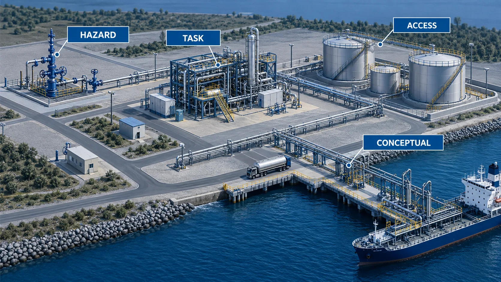
Eight input groups that make an enquiry usable
1. Jurisdiction and classification documents
State the country, authority having jurisdiction, owner specification, code/standard editions and project phase. Attach the current area-classification drawing, hazardous-area schedule and any equipment protection requirements.
For gas or vapour areas, record the required zone or Class/Division system, gas group, EPL/category or equivalent, temperature class, ambient basis and special project conditions. If combustible dust is also present, treat it as a separate hazard path; the combustible-dust lighting guide explains the additional inputs.
Do not ask a luminaire supplier to classify the site from a photo, process name or material safety data sheet alone.
2. Process and operating states
Identify normal operation, start-up, shutdown, purging, draining, sampling, loading, maintenance and foreseeable abnormal conditions that affect the approved classification or work task. Include ventilation assumptions and any temporary configuration relevant to the lighting location.
This does not replace the formal classification study. It tells the lighting and electrical teams which drawing revision and operating basis they are designing against.
3. Environmental exposure at the mounting point
Record the actual ambient temperature range, process heat, humidity, condensation, rain, washdown, salt, hydrocarbons, chemicals, UV, dust, vibration and impact exposure. Separate each mounting location: an open jetty, sheltered compressor module and indoor switch room do not share one environmental description.
An IP rating does not establish explosion protection, chemical compatibility, corrosion life or offshore suitability. Those claims need their own evidence.
4. Lighting task and geometry
Provide a dimensioned plan and elevations. Mark mounting points, heights, orientation, structures, pipework, vessels, stairs, handrails, equipment, vehicles and shadow-producing obstructions. Define the working planes and viewing directions for operation, inspection, reading instruments, access and emergency movement.
State the maintained illuminance, uniformity, glare, color, flicker and emergency criteria from the applicable project authority. Do not convert lumens or beam angle into spacing or guaranteed lux. Request the exact IES/LDT file for the offered optical variant and calculate the real geometry.
5. Electrical supply and controls
State voltage, tolerance, frequency, earthing arrangement, switching groups, control protocol, dimming behavior, sensors, surge/lightning coordination and emergency or backup-power interface. Record whether the equipment must restart in a defined state after power restoration.
Controls and emergency functions can change the ordering code, internal components, certificate scope, operating temperature and document set. Do not treat them as accessories added after approval.
6. Cable entry, wiring and mounting interfaces
Define the cable or conduit system, cable construction and diameter, entry thread, gland/stopping-plug requirements, adapter policy, drain/breather requirements where permitted, earthing/bonding and sealing method. Include mounting loads, bracket/interface drawings, wind or vibration data and orientation restrictions.
IEC 60079-14:2024 covers design, equipment selection, installation and initial inspection of Ex electrical installations, including documentation and competency. The applicable national rules, certificate conditions and exact manufacturer instructions govern the installation.
7. Maintenance and shutdown constraints
State how the luminaire can be isolated, reached, inspected and cleaned; who is competent to perform the work; and what shutdown windows exist. Include platform, ladder, scaffold or lifting constraints and whether access can disturb process equipment.
IEC 60079-17:2023 addresses inspection and maintenance factors specifically related to hazardous-area electrical installations. It does not replace general electrical maintenance, equipment verification or repair requirements. A blog must not become an energized-work or Ex-repair procedure.
8. Procurement and documentation requirements
For every offered ordering code, request the current datasheet, complete certificate and schedule/annex, marking drawing or nameplate record, instructions, dimensional drawing, wiring/entry details, accessory compatibility, photometric file and any required test records. Specify document language, digital format, quantity, delivery location and approval schedule.
If the certificate covers a family but the offer uses a suffix, optic, driver, entry or emergency variant that is not traceable through the documents, mark it unresolved.
Match exact evidence, not marketing categories
The current general IEC equipment requirements are in IEC 60079-0:2026. That publication defines construction, testing and marking requirements, but it does not prove that a TORMIN or third-party model has been certified. Only the exact current certificate and associated schedule can establish the covered model/variant and conditions.
Use four evidence columns in the technical bid evaluation:
| Requirement | Project evidence | Supplier evidence | Acceptance question |
|---|---|---|---|
| Hazardous-area suitability | Classification drawing and equipment schedule | Exact certificate, schedule and marking | Does the exact offered code match the required framework and conditions? |
| Environmental suitability | Site environmental schedule | Materials, coating/seal data, ambient range and tests | Are all exposures supported for this location? |
| Lighting performance | Task criteria, geometry and maintenance basis | Exact photometric file and calculation inputs | Does the calculated result meet every required task plane and constraint? |
| Installation and lifecycle | Wiring, mounting, access and maintenance strategy | Instructions, drawings and inspection information | Can the equipment be installed, inspected and maintained as designed? |
Category membership is useful for discovery, not acceptance. TORMIN’s explosion-proof lighting category contains candidate form factors; the exact documents decide whether a specific model can proceed.
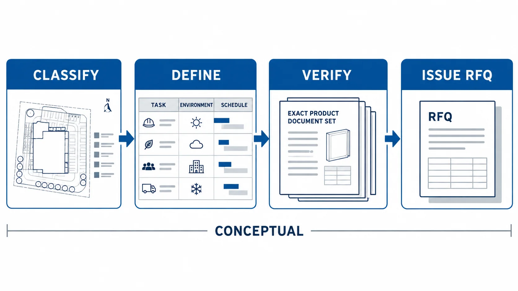
Copy-ready oil and gas lighting RFQ block
Project / package:
Country and authority having jurisdiction:
Owner specification and adopted code editions:
Project phase and required approval date:

Location ID and process area:
Area-classification drawing number and revision:
Required Zone/EPL/category or Class/Division approval:
Gas or dust group and temperature requirement:
Ambient range and special conditions:

Moisture, salt, chemical, UV, vibration, impact and washdown exposure:
Supply, frequency, controls and emergency function:
Cable/conduit system, entry thread, gland and sealing requirements:
Mounting position, height, orientation and load constraints:
Isolation, access and maintenance method:

Task planes and viewing directions:
Maintained-lighting, uniformity, glare, color and flicker criteria:
Dimensioned plans, elevations, reflectances and obstructions attached:

Exact certificate scheme and document language required:
Datasheet, certificate schedules, instructions, drawings and photometry required:
Quantity, destination and schedule:
Route the project through the right TORMIN surfaces
Use the TORMIN Oil & Gas Lighting solution page for the broad application route and the standards and certifications page to locate available first-party evidence. Neither page substitutes for exact model documents.
Send the completed RFQ block and drawings through the TORMIN contact page or sales@tormin-lighting.com. A candidate recommendation should follow—not precede—the project’s hazardous-area, environmental and photometric inputs.